Controlling a Hobby Servo using an Arduino
We will control a hobby servo using an Arduino (AVR) microcontroller by outputting a PWM (Pulse Width Modulation) signal from the
microcontroller to the servo. We will be using much of the information from the previous
video and information on the fundamentals of PWM. We will also learn some new jargon that is specific to the Arduino
microcontrollers.
First, we will need to select a timer and the correct WGM (Waveform Generation Mode) within this timer that will be
appropraite for the servo. Next, we need to select the PWM period that will work with the servo. The servo used in the
video accepts a period 20 miliseconds long and we will take advantage of the ICR1 register to create this period. To do this,
we will need to determine a prescaler so the timer uses the microcontroller's clock source properly, we will need
to set the PWM to be in the correct mode, inverted or non-inverted, where the pulse happens at the beginning of the period,
or at the end of the period and finally, we will need to derermine which OCR (Output Capture Register) we will use, 1A or 1B.
First, let's detemine the WGM (Waveform Generation Modes) in the Arduino. There are two main types of waveform generation modes, the fast
PWM and the phase correct PWM as we were introduced to in the previous video.
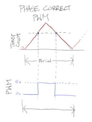
The phase correct PWM creates the pulse at the midpoint of the period. How does this happen? With the phase correct mode, the
Arduino timmer counts up and then counts down. At the beginning of the period (when the timer count is at 0), the time counts up to a
set number you store in the Arduino's register (ICR1), or let the time count up to the maximum value of an 8-bit, 9-bit or 10-bit
number which is 256, 512 or 1024 respectively. As the timer counts up to this maximum number you determine, you will set
another register to bring a pin high (the pin that will output the PWM signal) when it gets to specific timer count. This
timer count will be hit twice, because the timer is climbing, and then when it hits the maximum, will start falling. As the
timer gets to the same count as it is counting down, the PWM pin will go low. You can also set any pin to output a PWM signal
because you always have access to the timer count and you already know how to set a pin high and low.
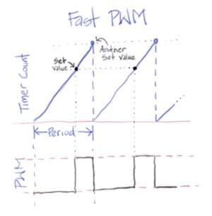
Then there is the Fast PWM, where the timer will count up, then reset to 0 when it hits the desired maximum count value that
you set. The timer will not count back down in fast PWM, just reset back to 0 then starts counting up again. The pulse of the
PWM signal will occur at the beginning or the end of the period, depending if you are in inverted, or non inverted mode. Here
is how the pulse is formed in the fast PWM mode. In non-inverted mode, you will set a particular value for the timer to hit
for the PWM signal to go high. When the timer is 0, the PWM signal is low, when the timer hits the set value, the PWM will be
high until the timer goes to 0 again.
In this particular example in the video, I use the ICR1 to set the top of the timer count, and I also use fast PWM (WGM13,
WGM12 and WGM11 are set in the Timer Counter Control Registers TCCR1A and TCCR1B). The servo doesn't need to have phase correct PWM.
Simply setting this register to a desired maximum value will force the timer to reset to 0 when that number is reached. This will
create our period.
TCCR1A |= 1<<WGM11;
TCCR1B |= 1<<WGM13 | 1<<WGM12;
The hobby servo that I am using requires a 50 Hz signal. What does that mean? The servo will need a PWM signal that occurs 50 times
per second. What portion of a second does 50 Hz equal? If we divide one second by 50, we get 1/50 = 0.02 seconds. That is the same
as saying 2 deciseconds, or 20 miliseconds (ms). Deciseconds are generally not used, but miliseconds (ms) are. So, we need to send
a pulse every 20 (ms), so that means our period must be 20 ms in length, and the pulse will happen within this 20 ms period.
Now we need to determine the timer maximum count. To figure out what 20 ms is for our timer, we need to consider the clock speed of
the microcontroller, since the timer runs off of the clock cycles. Every time the clock ticks, the timer will count up. If the
microcontroller is set at 1 MHz or 1,000,000 Hz, then we can determine that the timer count maximum would need to be 1,000,000/50Hz
which is 20,000. So, the ICR1 can be set at 19,999 since the counting starts at 0, not 1. If you have a different clock speed, say
16,000,000, then just use the F_CPU value in a formula, like F_CPU/50 and you will get your ICR1 number. But hold on, what if the
number is more than 65,535 which is the maximum number allowed for the timer? This is where you will need a prescaler for the timer
which is the CS10..12 bits. Because we don't need a prescaler, we only need to set the CS10 bit located in the TCCR1B register.
ICR1 = F_CPU / (Servo acceptable Hz value); //Use a prescaler if the ICR1 has a value above 65535
We will use the inverted mode for this example, which starts the PWM signal low at the 0 timer counter. The OCR1A is where we will
put the value for the pulse to start. The OCR1A will have a value within the 19,999 maximum. To set the inverted mode, we need to
set the COM1A1 and COM1A0 bits located in the TCCR1A register. If we wanted to use non-inverted mode, then the COM1A1 would need to
be set, but the COM1A0 would not need to be set. Oh yeah, if you wanted to use OCR1B instead of OCR1A, you just need to use COM1B1
and COM1B0 instead.
TCCR1A |= 1<<COM1A1 | 1<<COM1A0; // Inverted mode
Since we are using the inverted mode in the example, the OCR1A value would need to be 19,999 subtracted by the
actual width of the pulse (measure by the number of timer count cycles) since the pulse will be at the end of the period. For
example, if the pulse width is 2 ms, this would be equivalent to 2000 timer cycles. So, the OCR1A value is 19,999 - 2000 = 17,999.
OCR1A = ICR1 - (Pulse Width);
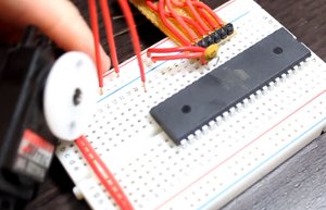 The servo is plugged into the circuit
(breadboard) with the power (red wire) going to the + rail and the GND (black wire) going to the - rail. The signal wire of the
servo, which is the yellow wire, is plugged into the OCR1A pin which is pin number 19 on the ATmega 32. You will need to consult
the datasheet for your microcontroller to determine where the OC1A pin is located if you are using a different microcontroller.
The servo is plugged into the circuit
(breadboard) with the power (red wire) going to the + rail and the GND (black wire) going to the - rail. The signal wire of the
servo, which is the yellow wire, is plugged into the OCR1A pin which is pin number 19 on the ATmega 32. You will need to consult
the datasheet for your microcontroller to determine where the OC1A pin is located if you are using a different microcontroller.
The following program will set the servo's position at the 2 ms rotation mark. This is a maximum that the datasheet specifies, but
the servo did not reach the 180 degree angle. You may need to tweak the numbers to get as close as possible to the extremes of your
servo, but don't go too far, or you will damage the servo (strip the gears). Test the servos rotation by changing the OCR1A number
within the datasheets minimum and maximum specifications. My datasheet specified .9 ms (900 timer ticks) as the minimum.
#include <avr/io.h>
int main(void)
{
DDRD |= 0xFF;
TCCR1A |= 1<<WGM11 | 1<<COM1A1 | 1<<COM1A0;
TCCR1B |= 1<<WGM13 | 1<<WGM12 | 1<<CS10;
ICR1A = 19999;
OCR1A = ICR1 - 2000; //18000
while (1)
{
}
}
Let's have some fun and have the servo move back and forth continually. The instructions will need to be within the never ending
while loop. We will need to add a delay. If a delay was not added, the servo would not move and here is why: it takes time for
the servo to reach a position since this is a mechanical device. You can see in the video that the servo took about a tenth of
a second to reach from one rotational angle to the other. The instructions take one millionth of a second to perform an instruction
and the servo would not even be able to move a fraction of the rotation within that time frame. So, we need to introduce a time
delay between each setting of the horn's position.
#include <avr/io.h>
#include <util/delay.h>
int main(void)
{
DDRD |= 0xFF;
TCCR1A |= 1<<WGM11 | 1<<COM1A1 | 1<<COM1A0;
TCCR1B |= 1<<WGM13 | 1<<WGM12 | 1<<CS10;
ICR1A = 19999;
OCR1A = ICR1 - 2000; //18000
while (1)
{
OCR1A = ICR1 - 800;
_delay_ms(100);
OCR1A = ICR1 - 2200;
_delay_ms(100);
}
}