Microcontroller - A Beginners Guide - Writing the First Program to Turn On an LED
and Transferring the Program into the Microcontroller
I know that you are ready to write the first program. You have been through a lot
so far! While we are on the subject, let's recap the events. You went out and purchased
the AVR Atmel Microcontroller
of your choice. I chose the ATMega32
for my uses. You were introduced to the
concept of microcontrollers how they work; and were also introduced to the
programmer, the device that helps transfer the program into the microcontroller.
You
built a convenient interface that is used to connect the SPI pins to the
correct pins of the microcontroller. You verified that the
programmer (USBTinyISP) drivers were installed correctly for the 32-bit
and 64-bit versions of Windows (XP, 7 and Vista). You also installed the programming
environment installed
the "Programming Environment" called WinAVR so that you can have an environment
in which to write your program, and then transfer it into the microcontroller. And
to make sure that everything functions correctly, you used avrdude to
tested the programmer while plugged into the computer and the microcontroller.
Recall that this program is the program transfer utility to move our compiled program
into the memory on the microcontroller. Finally, you built the first circuit so
that we could have something to write a program for. Whew... that was a lot! But
since you jumped through all of those hurdles, the hard work is over and it's smooth
sailing from here on. Hopefully you were able to get through the previous steps
without any problems--so now let's get on with our first program.
For the sake of simplification, let's categorize the function of the microcontroller
into three categories: Control, sensing and communication. We'll leave the details
of how to develop each of these functions, and delve into these details as we write
the various programs. Note that there are many ways to program these functions.
For the first program, we'll make the microcontroller "control" something. And as
you know from the previous post, we'll be using an LED for this purpose. Basically,
we will turn the LED on. Yes I know... boring, right? Well I need to start somewhere!
As I take you through the experience of programming, I will add more complexity
a little at a time so you are easily able to wrap your head around these important
concepts.
 So at this point you're probably asking...how do we make a program to control an
LED? Well, it's really easy: We will simply tell Pin0 on PORTB to output 5 volts.
Remember that this is the pin to which the positive lead (anode) is connected. The
first key in this scenario is "output, " and the next is "5 volts." There is a way
we can tell a particular pin to be set to be an output from the MCU. Once a pin
has been set to provide output, you will then be able to control that pin and make
it either high (5 volts) or make it low (zero voltage). And since there are only
two states for this pin in the output mode (5v or 0v), and only two states for the
mode itself (input or output), you only need to set the value to either logical
1 or a 0. Note that this must be accomplished for each pin we wish to use in our
circuit. But before we get to plugging in a 1 or 0, let's talk about input versus
output. When a pin is in input mode, it is listening for a voltage. When the pin
is in output mode, the it can be charged at 5v, or not charged at 0v. That's it!
So at this point you're probably asking...how do we make a program to control an
LED? Well, it's really easy: We will simply tell Pin0 on PORTB to output 5 volts.
Remember that this is the pin to which the positive lead (anode) is connected. The
first key in this scenario is "output, " and the next is "5 volts." There is a way
we can tell a particular pin to be set to be an output from the MCU. Once a pin
has been set to provide output, you will then be able to control that pin and make
it either high (5 volts) or make it low (zero voltage). And since there are only
two states for this pin in the output mode (5v or 0v), and only two states for the
mode itself (input or output), you only need to set the value to either logical
1 or a 0. Note that this must be accomplished for each pin we wish to use in our
circuit. But before we get to plugging in a 1 or 0, let's talk about input versus
output. When a pin is in input mode, it is listening for a voltage. When the pin
is in output mode, the it can be charged at 5v, or not charged at 0v. That's it!
There are many ways to do this. This is not to confuse you, but rather to make things
simpler. I will be introducing you to one of the many ways to accomplish this task,
and later I will explain some other methods while writing other programs. Note however
that while this first method is great for introducing the concept, it's probably
not as good in practice. Therefore you will see other methods in future programs
that will leave contextual pins (those pins on either side of the pin of interest)
unaffected, as they may very well have been previously set in the program. But since
we're writing a simple program, we won't worry about this complexity at this time.
To pick the output mode for a pin, you will use the Data Direction Register (DDR).
Oh man! What is a register?!? Don't let this worry you. A register is simply a memory
location that makes the microcontroller react in some way. We use a register to
set a state for the microcontroller, or make the microcontroller do something. It's
like reflexes, or tickles. When a person tickles another person, it invokes laughter.
We can make the MCU do something by setting a specific value in a register. That's
all you need to know at the moment.
So when you use the DDR register, you are able to set the pin to either output data,
or accept data input. But we said input or output, now you're saying data also.
The term "data" used here simply just adds another dimension to this idea in the
form of "time." If you make a pin 5 volts, then zero volts, and then 5 volts again...you
are actually sending 1s and 0s. To the pin, this is nothing more than a high (5
volts) state, and then a low (zero volts) state: The MCU sees this high/low logic.
And you can also receive data in the same way.
There are several ways to set pin0 for port B to output. One way to do this is to
write:
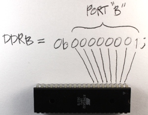
DDRB = 0b00000001;
Let me explain. "DDRB" refers to the Data Direction Register for port B; "0b" is
to tell the compiler that what follows is the binary expression of a number; and
the "1" on the end denotes the pin 0 position (the first pin in port B). Recall
that there are 8 pins for port B; pins 0 though 7. There are also 8 digits in our
line of code. So each digit represents a pin on the port, and we can use the individual
digits to specifically refer to any one of the pins in port B. So the '1' at the
end of our code statement refers to the first pin in port B, which in this case
is pin 0. (Recall that C and C++ are zero-based languages, so the first index of
a data structure refers to is the zero'th element; the second index refers to the
first element, etc.) We really don't need to get any more complex at this point,
as this will be covered in much more detail in future tutorials. However if you
would like to know more about the
binary system, check here.
 Now we need to apply 5v to the pin. This works just like the DDR code statement
we used above. We will use a binary number to put 5v on that pin (pin 0) using this
statement:
Now we need to apply 5v to the pin. This works just like the DDR code statement
we used above. We will use a binary number to put 5v on that pin (pin 0) using this
statement:
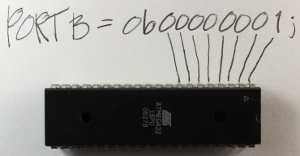
PORTB = 0b00000001;
The only difference between this and the previous statement is that we are now using
the PORT register. This register knows the pins of that specific port, and gives
us access to specify the actual data value (logical 0 or 1) for these pins.
Now we need to talk a bit about the overall structure of our program. All programs
need a specified place to start the execution. It's like giving someone a set of
instructions on how to make a cake without telling them which step to start on.
The "main" function is the place where all C/C++ programs start execution. So we
will create a main function.
int main(void)
{
}
In order for the program to understand the DDR and PORT register information and
how these work within the microcontroller, an include statement must be added that
contains all of the information about the AVR microcontrollers. This include statement
will probably be in all of your programs.
#include <avr/io.h>
int main(void)
{
}
When the compilation process starts, the pre-processor portion of the compiler looks
in the "avr" directory for the "io.h" file. The ".h" extension here indicates that
this is a header file, and (as its name implies) the code within that file will
be inserted at the beginning (head) of the source file you are creating. Now we
can insert the DDR and PORT statements into our code, since the inclusion of the
io.h header file has informed the compiler about them.
#include <avr/io.h>
int main(void)
{
DDRB = 0b00000001; //Data Direction Register setting pin0
to output and the remaining pins as input
PORTB = 0b00000001; //Set pin0 to 5 volts
}
Now the direction of the pin0 is set to output, with a value set at 5v. But we are
still not finished. We need to keep the microcontroller running indefinitely, so
we need a routine to do this. This is called an endless (or infinite) loop. The
infinite loop makes sure that the microcontroller does not stop performing its operations.
I will explain this in more detail when we have stuff to do within this loop. There
are several types of loops we can use for this purpose, but for this demonstration
I will use the while loop. It means the same in English as it does in code: For
instance, "while" I have my hand up, you should keep clapping.
#include <avr/io.h>
int main(void)
{
DDRB = 0b00000001;
//Data Direction Register setting pin0 to output
and the remaining pins as input
PORTB = 0b00000001;
//Set pin0 to 5 volts
while(1)
{
//Code would be in here if it needed to execute over and
over and over ... endlessly
}
}
Note that we use a '1' as the argument to the while loop, because anything other
than '0' is a logical true. Therefore the while loop condition will never be anything
other than logically true, and the program will continue to execute indefinitely
(i.e.; I keep my hand raised).
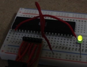 So, here is the fruit
of our labor. It was a long ride so far, but I promise, everything from here on
will be gratifying and far less time consuming. In the next video and instruction,
we will make the LED blink. We will investigate how to create a delay so the LED
does not blink so fast that it looks like it's not blinking.
So, here is the fruit
of our labor. It was a long ride so far, but I promise, everything from here on
will be gratifying and far less time consuming. In the next video and instruction,
we will make the LED blink. We will investigate how to create a delay so the LED
does not blink so fast that it looks like it's not blinking.