Microcontroller - A Beginners Guide - Introduction and Interfacing an LCD (Liquid
Crystal Display)
The microcontroller is a wonderful piece of engineering and it can do many things (with the help of some great programming),
but it is still an opaque black box. If you want it to share information, or show you what it is trying to do, you need
to hook-up (interface) an output device. An output device is a thing that provides you a way to show information from the
microcontroller. That is to say, the output device allows the microcontroller to "output" information to the "device". We
have already worked with another output device, called the LED (Light Emitting Diode), which gives off light when you program
it to do so. We will take an in-depth look at interfacing and programming the LCD (Liquid Crystal Display).
The LCD is a much more informative output device than a single LED. The LCD is a
display that can easily show characters on its screen. LCDs range in size, price
and configuration, from having a couple of lines to large displays. Some are even
very specifically designed for a single application, having only that ability to
display set graphics. We will be usng an LCD that has the ability to display four
(4) lines of characters that has a 20 character line length. This is quite sufficient
to show quite a bit of information. Another popular LCD has 2 lines and 16 characters
per line.
In this video tutorial, we will look at how the LCD receives information and control,
and the requirements to make sure the information is sent to the LCD in the way
that it can appropriately accept information. So, what does all that mean?
First, we have a speed discrepancy between the LCD and the microcontroller. The
microcontroller is much faster than the LCD, so the microcontroller's program must
be fully aware of this and compensate for the time that the LCD is busy working
on things you told it just prior. Fortunately, the LCD can inform us of this busy
status. So, we will create a function to wait until the LCD is not busy. For the
LCD to accept information from the microcontroller, or let it give you information,
we must turn its enable pin on and off while the information is present for the
LCD to accept.
 So
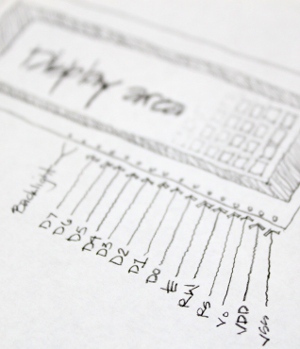
now is probably a good time to talk about the pins on the LCD. The most basic of
the pins are the power pins for the display to be able to function in the first
place. There is a VDD pin for 5 volts and a VSS pin for ground. There is a V0 pin
for the adjustment of the LCD contrast. Some LCDs even have an LED backlight and
are generally the last two pins.
So
now is probably a good time to talk about the pins on the LCD. The most basic of
the pins are the power pins for the display to be able to function in the first
place. There is a VDD pin for 5 volts and a VSS pin for ground. There is a V0 pin
for the adjustment of the LCD contrast. Some LCDs even have an LED backlight and
are generally the last two pins.
Just like the microcontroller, the LCD has a row of 8 pins to serve as its port.
The pins that serve as its port is D0, D1, D2, D3, D4, D5, D6 and D7. These pins
are generally used to pass information into the LCD, but it can also be set to pass
information back to the microcontroller. I know, you are probably thinking, "but
Patrick (that's me) told me this is an output device?!?". Well, sure, it is, but
from time to time, it will need to inform you of its state (if it is busy or not).
Two types of information can be passed through these pins: data to display on the
LCD screen, or control information that is used to do things such as clearing the
screen, controlling the cursor position, turning the display on or off, etc. These
data pins are connected to the pins of the desired port on the microcontroller.
For example, if you wanted the LCD to be connected to PORTB, the D0 would be connected
to Pin0 of Port B, and: D1-PortB Pin1, D2-PortB Pin2, D3-PortB Pin3, D4-PortB Pin4,
D5-PortB Pin5, D6-PortB Pin6 and D7-PortB Pin7. This way, there is a pin to pin
consistency, and if you pass a character in the form of a hexadecimal number, the
LCD will receive it in the proper way. If not, there will unexpected results, unless
you use a unique form of byte structure, but don't let that get in your way.
There are other pins on the LCD that help the LCD accept information, and
tell the LCD to receive a character or control, or control the read or write
(input or output) function of the pins. Just to clarify, the read/write
is microcontroller centric: the LCD "read" mode is the process of passing information
from the LCD to the microcontroller (microcontroller port set as input or reading
or listening).; the LCD "write" mode is passing information from the microcontroller
to the LCD (microcontroller set to output or writing).
The pin on the LCD that is responsible for the read and write state is labeled R/W.
The pin on the LCD that is responsible for whether the infomation sent is a character
or a control, is the RS pin (Register Select). And the pin that helps the LCD accept
informatin is called the EN pin (Enable).
There are three basic things you will want to do with an LCD for the proper functioning
(more advanced functions can be performed with these three fundamental routines):
(1) to make sure the LCD is not busy; (2) Control the LCD's cursor, or display function;
and (3) Write a character to the LCD for it to display. Each of these will require
its own process:
(1) Checking if the LCD is busy (If you try to display a character to the LCD while
the LCD is busy, then the LCD will just ignor the character and it will not be displayed).
- We set the port to receive data on the microcontroller (Data direction as input).
- We put the LCD in read mode (RW on).
- We put the LCD in command mode (RS off).
- And the port now magically contains the data from the LCD (D7 pin will be ON if
the LCD is busy and OFF if the LCD is not busy).
(2) Send a command to the LCD
- We check to see if the LCD is busy (Perform the steps in #1 above).
- We set the port direction as output so we can send information to the LCD.
- We turn RW off so we can write.
- We turn RS off for command mode.
- We fire up the data lines with the command we want (simply making the port equal
to a number that associates to a specific command).
- We turn on the enable and then turn it off.
- The LCD will magically perform the command.
(3) Send a character to the LCD: This is the same as sending a command except the
RS is on and the port will equal the character corresponding to the ASCII code.
So, we are really just turning pins on and off, just like we did with the LEDs from
the past tutorials. It's as simple as that. The only catch is that they must be
done in the correct sequence.