
Microcontroller - A Beginners Guide - Introduction
Microcontroller - A Beginners Guide - Introduction
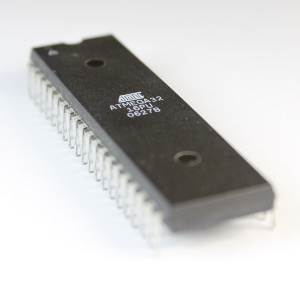 This is the first in a long line of tutorials aimed to provide a beginners guide and tutorial based around the Atmel AVR Atmega32 microncontroller. I will show you, through examples and projects, how to program and provide functions for this microcontroller and what the uses and applications are.
With microcontrollers in general, it is good to know that these little chips are found everywhere. You can find them in microwaves ovens, new applicances, automobiles, televisions, etc. These microcontrollers control and sense the surrounding electronics and environment. For example, microcontrollers can provide output to a display, motor, LEDS, etc., sensing the environment, such as tilt using an accellerometer, light, angular velocity using a MEMS (Microelectromechanical System) gyroscope, sound, encoders for movement, temperature, and button or keyboard input.
To give you a basic understanding of the microcontroller, the AVR Atmega32 microcontroller is considered to be a computer on a chip. The microcontroller is able to execute a set of instructions in the form of a program. The program language that I will be using for theseprojects is C++. To giv ethe usersof this website the best opportunity to learn, the C++ programs will be explained is great detail.
The really cool thing about microcontrollers is that you have control over all the pins. For a beginner, this can be a difficult concept to understand, especially having no experience with electronics. Don't fret, I will walk you through each tiny detail. Each pin has a special assignment, or can be used as an input or output feature, with a few exceptions, the power pins.
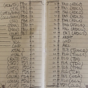 On the left hand side of the chip, looking at it form the top and the little triangle is at the top left, there are 20 pins (this is a 40 pin microcontroller). The first starting from the top left are the PB0-7 pins. That's a total of 8 pins as the index of these pins and most everything in the program starts with an index at 0. This set of pins are called "Port B" and there are 3 other ports labeled from A to D. These ports can be set to receive information and is called INPUT and they can be set to send voltage out in some form called OUTPUT. General power pins to receive the power for the chip called VCC and GND. All but one pin of Port D (PD0-6) is also located on the left side (lower section). PD7 (Pin 7 of Port D) is all alone starting the right hand side of the microcontroller.
Continuing on the right side, and the ending of Port D, Port C continued from the lower corner up. From there on, may favorite pins continue, the analog to digital pins. These pins have the capability to sense the environment with the help of components that feed these pins an analog voltage. Dopn't worry about not understanding analog or even digita at this point, it will be explained in greter detail later. These analog to digidal converter pins compose Port A.
One example of the use of the analong to digital conversion would be, say, sensing the temperature. You can connect a component that converts temperature to a level of voltage called a thermistor to one of the Port A pins and the microcontroller will convert this voltage to a number from 0 to 255 (an 8-bit number - higher resolution is possible at 10-bits). The program that is written and stored into the microcontroller can use this temperature and respond in a specific way. For example, if you have the thermistor against a boiling pot, the microcontroller can respond and provide an output to another pin that beeps, or flashes a light.
Other features of this and other microcontrollers, other than the actual programming is the programming space (where the program is stored in the chip and how much space you have), memory, or space for data and variables that the program will use, and finally, there is a clock built into the chip that counts. The counting can be in many different speeds depending on the speed of the chip and the divisor that is selected for the speed. This is starting to get complicated, so I will back up. The counting can be in seconds, miliseconds, microseconds, or whatever you determine for the program and application that you select.
As this tutorial series is based on examples, I will provide a great deal of detail. Of course, the detail for the introduction would be impossible, and if you are very adventureous, you can take a look at the datasheet and manual for this microprocessor, but don't let that huge document sway you from wanting to learn this most incredible technology. Once you lear, there is no limit to the application, from tiny robots, to extremely large scaled architectural wonders that move and give off spectacular lighting effects, sometimes that interact with the environment.