Latest Tutorials and News
Software Debouncing in Detail on ARM Microcontrollers

In this video, you will get a ton of detail on software debouncing. I demonstrate the bouncing on the push button and
show the results on an oscilliscope. Additionally, I show how to program the software debouncing code into a library
for very easy implementation within the while loop. This is a must see video, and by watching, you are supporting
the content that I serve.
Code Tutorial: Communicating the I2C / TWI (2-wire interface)
I take you by the hand through the process of progrmming the I2C / TWI protocol in this video. This is exclusive
content that, if you are willing, you can become an expert in communicating with the I2C. This is territory that
few will master, but if you watch the video, you will!
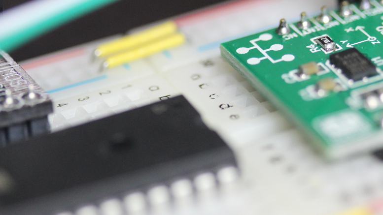
In the video, I demonstrate the programing needed to communicate with a slave through the I2C protocol. The slave, in
this case, is an accelerometer (ADXL 345). I take you through the complete process of programming and testing. In
the programming portion, you will learn what is required by the master and the slave to establish the communication.
In testing, I probe the SDA and SCL lines and show you the data that was transmitted over these lines and what the
slave returned.
Controlling a Hobby Servo using an Arduino (AVR) Microcontroller
We will control a hobby servo using an Arduino (AVR) microcontroller by outputting a PWM (Pulse Width Modulation) signal from the
microcontroller to the servo. We will be using much of the information from the
previous video and information on the fundamentals of PWM.
We will also learn some new jargon that is specific to the Arduino microcontrollers.
First, we will need to select a timer and the correct WGM (Waveform Generation Mode) within this timer that will be
appropraite for the servo. Next, we need to select the PWM period that will work with the servo. The servo used in the
video accepts a period 20 miliseconds long and we will take advantage of the ICR1 register to create this period. To do this,
we will need to determine a prescaler so the timer uses the microcontroller's clock source properly, we will need
to set the PWM to be in the correct mode, inverted or non-inverted, where the pulse happens at the beginning of the period,
or at the end of the period and finally, we will need to derermine which OCR (Output Capture Register) we will use, 1A or 1B.
Read on...
Introduction to PWM for the Arduino AVR Microcontrollers
PWM stands for Pulse Width Modulation and is the method to produce variable voltages using digital means. Typically,
variable voltages come from analog circuits, and digital circuits produce only two voltages, the high (5v, 3.3v, 1.8v, etc.)
or low (0v). So how it is possible that digital circuits can produce avoltage that is between the high and the low voltages?
If you bring a digital signal up and down, in a consistent manner, you will get a proportion of the voltage between the high
and low voltage. Imagine if a digital signal was pulsed high (5v) and low (0v) evenly, say the signal was in the high state
for 1 microsecond and in the low state for 1 microsecond, add a capacitor to smooth the signal, the voltage would measure 2.5
volts. Now, change the high voltage in the high state for 9 microseconds and in the low state for 1 microseconds, the voltage
would measure 90% of 5 volts, or 5v x .9 = 4.5 volts. The 90% is significant because the duty cycle is represented as a
percentage (%). The applications associated with PWM could be: thecontrol of motors, sound output, dimming LEDs, and producing
approximated analog waveforms. Read on...
Upcoming Tutorials:
SPI Communication (Chip to Chip)
Demonstration of the funtamental signal requirements and timings and then show examples of circuit and code to establish
communication.
PID and Encoder Control for DC Motor (Servo Basics)
Explain the fundamentals of encoders and how encoders can determine position for a greater mechanical system. This typically
requires PID (Proportional Integral Derivative) closed loop control and a thorough detailed explanation of this type of
control will be investigated. Various encoder types will be examined along with various types of motors and mechanical
advantage (gears, pulleys, chain, etc.). This will require some prerequisites in signal theory, which I will explain.
Introduction to Servos (video complete, official page soon to come)
I will do a run-down of the different types of servos out there and how they function.
I will also get into the details of closed-loop control.
Servo Control Using the Standard PWM Output (video complete, official page soon to
come)
PWM is the method used to control non-digital hobby servomechanisms. I will show
how to simply control the servo using the 16-bit timer and the PWM channels.
Servo Control Using the Output Pins (video complete, official page coming soon)
PWM will still be the method to control the hobby servo, but we may want the microcontroller
to drive more servos than the number of standard PWM channels will allow. Therefore
we will investigate a method that uses standard pins as PWM output to control many
servos.
Servo Control For Servos That Use Encoders
We will investigate the programming necessary to create a closed-loop system that
reads an encoder and positions a motor to create an overall servomechanism.
Controlling High AC Voltage Devices Using Relays (video complete, official page coming soon)
Do you want to control a household device? Using a relay and a spare output pin
on your microcontroller can do the trick. In this tutorial, we will control the
stuff that would be plugged into the wall outlet.
Controlling Higher DC Voltage Devices Using Mosfets
Enough of this 5v limit. With Mosfets, you can send higher DC voltages to devices
that would function better above the 5v limit that comes out of the microcontroller.
LED Control Using PWM
This tutorial is a precursor to motor control using PWM. We will control the brightness
of an LED and make it fade in and out softly.
LCD 4-Bit Mode
Is your LCD taking up too many pins? In 4-bit mode, the LCD will only need 4 data
lines--so your microcontroller can free-up 4 of the pins for other uses.
Introduction to Serial Communication (video complete, official page coming soon)
The basic fundamentals of serial communication will be explained in this tutorial.
Configuring and Communicating with the USART (video complete, official page coming soon)
Universal Synchronous Asynchronous Receiver Transmitter is the serial communication
function in the microcontroller. We will communicate to and from the computer via
RS-232 (with the help of the Max232 chip to adjust voltage levels), and we will
also communicate with a digital servo with a single wire to serve as both TX (Transmit)
and RX (Receive).
Motor Control Using PWM
This tutorial will delve into motor control. Using PWM, we will be able to increase
and decrease the speed of a motor and even change motor direction.
From Breadboard to PCB Prototype
This tutorial will explain the process necessary to create a schematic in Cadsoft
Eagle, layout the PCB (Printed Circuit Board) and build the prototype.
Using Transistors with Microcontrollers (video complete, official page coming soon)
Learn how to use transistors in your microcontroller projects.
Control of a Small Low-Current Stepping Motor
In this tutorial, a small low-current stepping motor will be controlled by the pins
of the microcontroller.
Control of Higher Current and Higher Torque Stepping Motors
A larger stepping motor will be controlled using Mosfets and a separate higher voltage
source; however the microcontroller will still be providing the control logic to
these Mosfets.
Control of Stepping Motors Using A Driver
As an alternative to Mosfets, I will select various driver chips on the market today
and use those to provide the high-powered driving current, again under the direction
of the microcontroller.
Control of Stepping Motors Using the Translator/Driver Combination
This is where things get interesting with stepping motor control, since the microcontroller
now becomes a processor for much broader control--with only the need to send out
step pulses and a high/low signal for direction control.
Using Alternative Clocks (video complete, official page coming soon)
Alternative clocks such as crystals, RC circuits and others will be explained and
connected to the microcontroller. We will use these devices to adjust the frequency
of the microcontroller.
Interfacing a Shift Register to Expand the Number of Output Pins
Imagine what you could do with many output pins! Do I hear...LED array? We can also
investigate using this device to communicate to the LCD with only a few wires.
Read a PIR Sensor
PIR (Passive Infra-Red) sensors will be explained and we learn to control these
devices with the microcontroller.
Read an Ambient Light Sensor
We will connect an ambient light sensor to the microcontroller, and check its reading
on the LCD.
Introduction to Interfacing with I2C (video complete, official page)
Inter-Integrated Circuit is a type of communication that is common with many sensors
and devices. I will probably start with an accelerometer that communicates using
this technology.
Read an IR Distance Sensor
An Infra-Red distance sensor will be connected to the microcontroller, and the information
will then be displayed to the LCD.
UltraSonic distance Sensor Reading
An ultrasonic distance sensor will be connected to the microcontroller, and the
distance displayed to the LCD.
Wireless Communication
I will do a survey of the wireless options that can be used with microcontroller
and explain each of them.
Radio Frequency Wireless Communication
We will communicate with another device using wireless radio frequency communication.
Communication using Xbee and Zigbee Devices
We will investigate the use of Xbee and Zigbee products for wireless network communications.
GPS Interfacing
A GPS module will be interfaced to the microcontroller. The information will be
parsed and delivered to the LCD. We may do some other interesting things with GPS
as well.
Other Microcontrollers, such as the ARM and PIC will get tutorials of their own.
When I begin with these tutorials, I will start another list.