Instructions
1

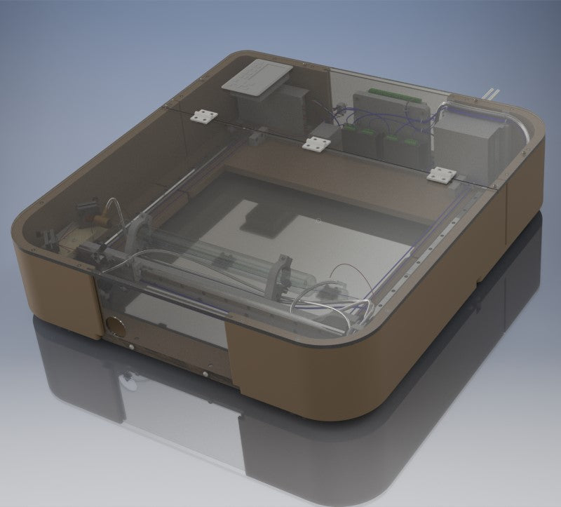
blackToothv2 Assembly Part 1
2
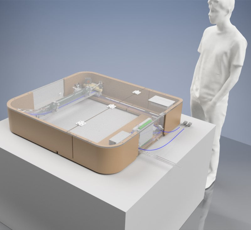
blackToothv2 Assembly Instructions Part 2
3
blackToothv2 Assembly Instructions Part 3
4
blackToothv2 Assembly Instructions Part 4
5
blackToothv2 Assembly Instructions Part 5
6
blackToothv2 Assembly Instructions Part 6
7
blackToothv2 Assembly Instructions Part 7
8
blackToothv2 Assembly Instructions Part 8
9
Laser Alignment Part 1
10
Laser Alignment Part 2
11
Laser Alignment Part 3
12
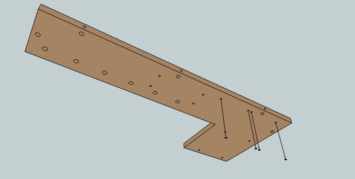
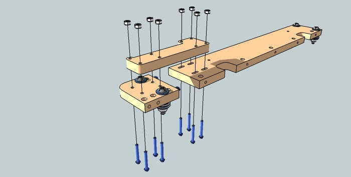
These following instructions are for the previous blackTooth version. Please refer to the video instructions and the paper/digital instructions that came with your kit if you have the newer version. With a 5/32” (~4mm) hex wrench, screw (4) #8 nut inserts into the bottom of the right-side base.
13
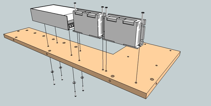
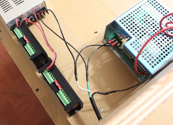
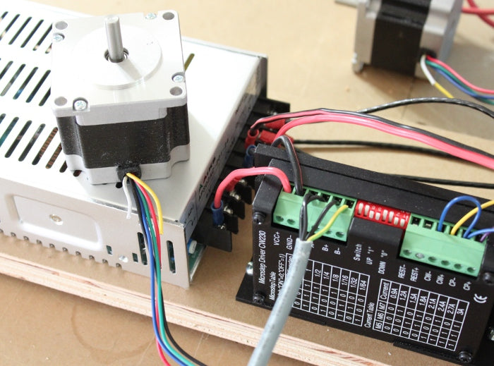
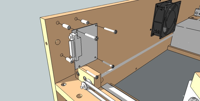
With a Philips head screwdriver, screw (4) M4 x 25mm screws with #8 washers up through the bottom of the base and into the Power Supply. Use (2) #8 x 1” screws to attach each motor driver as shown (they will screw into the nut inserts at the bottom of this wood base). After these parts are fastened, connect the power supply V+ and V- to the drives labeled GND and VCC. Each Driver should be wired independently, not daisy chained. Expose the wires in the female end of the extension power cable. Three wires will be in this cable, green, white and black and need to be wired to the power supply. Wire the green to the ground terminal, white to the N terminal and black to the L terminal. Take some 22 to 24 AWG stranded wire and connect them to the terminals from the driver labeled CP-, CW- and CP+. The CW+ will need to jump to the CP+ as this is common 5V.
14
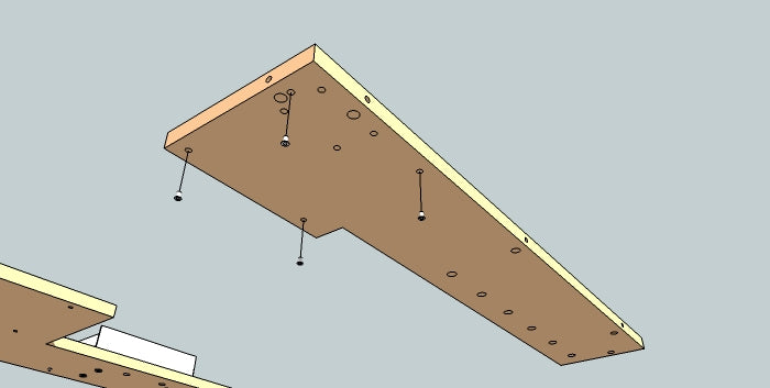
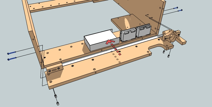
This step only applies to kits that include the computer. Insert (7) #8 nut inserts into the bottom of the left-side base as shown.
15
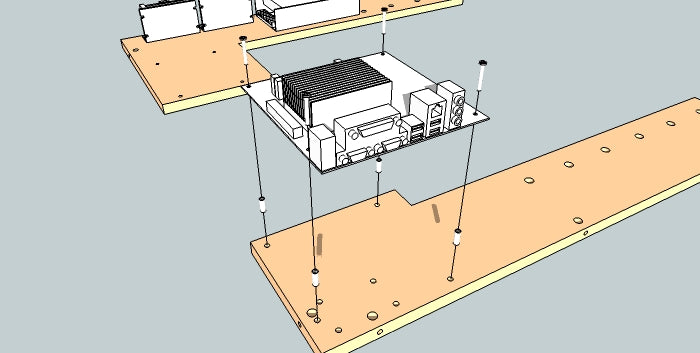
This step only applies to the kits that include the computer. Tap (4) plastic spacers into the holes as shown, then screw the motherboard onto these with (4) #8 x 1” screws. This would be a great time to wire/connect the motherboard components including the DC-DC converter that plugs into the motherboard for power, and hard drive with the SATA Cable power from the DC-DC converter
16
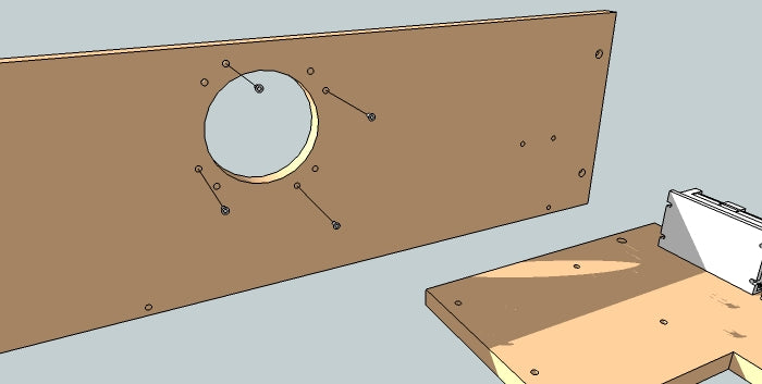
Insert (4) #8 nut inserts into the back panel as shown.
17
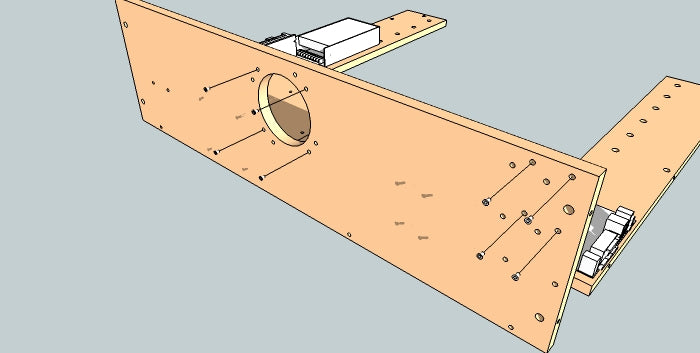
Insert (8) #8 nut inserts into the back side of the back panel as shown. If you have the USB breakout board, the 4 nut inserts on the right will not be needed.
18
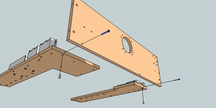
Attach the back panel to the 2 base pieces using (3) cross-dowels (“barrel nuts”) and (3) ¼” x 1.5” screws.
19
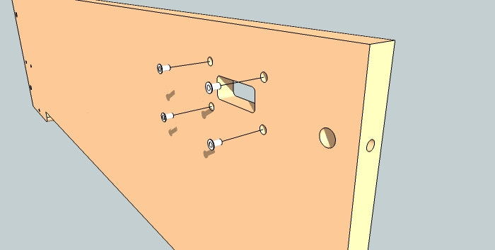
Insert (4) #8 nut inserts into the back side of the front panel. Place the LED panel on the opposite side of this part and fasten with four (4) #8 3/4 inch screws.
20
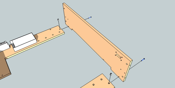
Attach the front panel to the 2 base pieces using (2) cross-dowels and (2) ¼ x 1-1/2 inch screws.
21
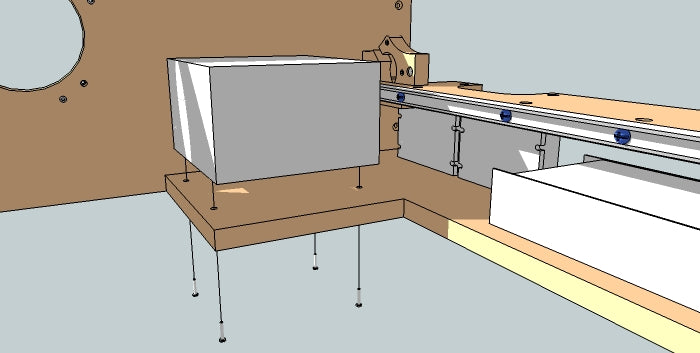
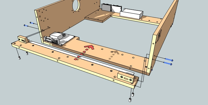
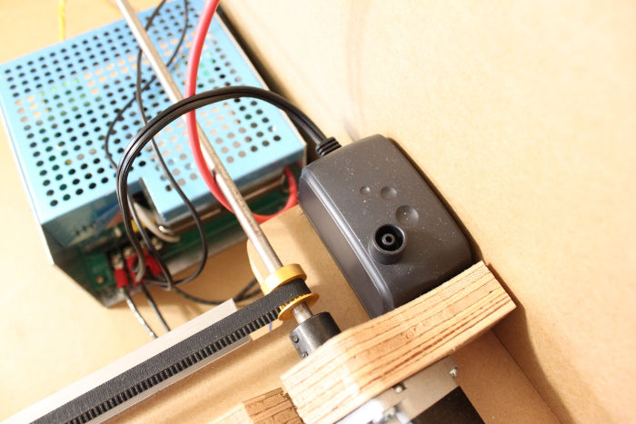
Attach the Laser Power Supply to the right-side base using (4) #8 x 1” screws and (4) #8 Nuts. Make sure the red wire is facing the near rail support. Wire the power from the power supply to an exposed extension cable. See wiring diagram at the end of the instructions for specifics.
22
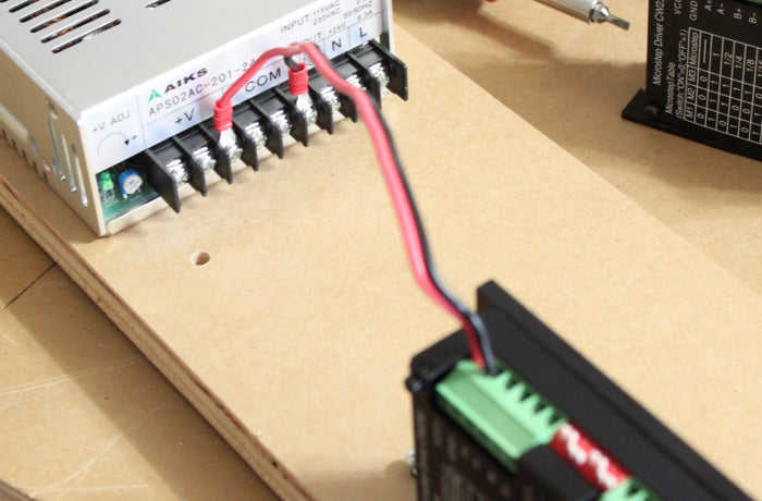
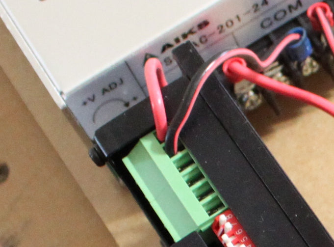
Connect the Y-Axis driver to the power supply. The V+ from the power supply is connected to the VCC terminal on the Driver. The V- from the power supply is connected to the GND terminal on the driver. For all connections to the terminals, the metal stranded part of the wire must be exposed first (strip the insulation off of the end of the wire). The length of each wire is 9.5 inches.
23
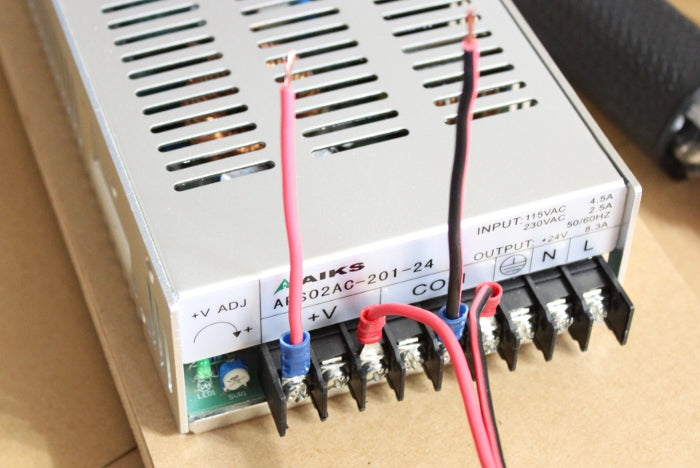
Connect the X-Axis driver to the CNC power supply. The instructions are the same as connecting the Y-Axis driver to the power supply. Each wire is 4.5 inches in length.
24
25
Connect the AC Power wires to the CNC Power Supply and to the laser tube power supply. Take the extension cable and remove the female end (the end that does not plug into the wall). Remove the insulation to expose the white (neutral), black (live) and green (ground) wires. The white wire is connected to the N terminal of the CNC power supply (10.5 inches) and on of the AC terminals of the laser tube power supply (6 inches). The green wire is connected to the CNC power supply terminal that has a ground symbol labeled on it (10.5 inches) and on the FG terminal on the laser tube power supply (6 inches). The black wire is connected to two toggle switches at the other side of the laser system (36 inches from the soldered connection and splits off in a Y for another 3.5 inches). The image shows only one wire leading to the far area of the system. At the end of that single wire, the wire splits off into a Y configuration.
26

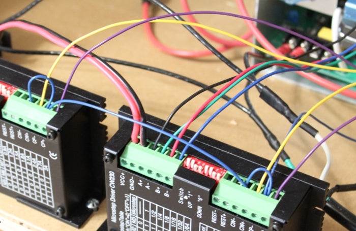
Connect the Y-Axis stepper motor to the Y-Axis Driver. The wires from the stepper motor are connected to the driver as follows: Black to A+ Green to A- Red to B+ Blue to B- Also, note the DIP switch settings. These are the correct settings for the stepper motor current and to enable 16 microsteps per step (microstepping @ 1/16).
27
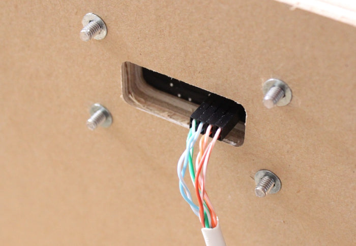
Connect the LED indicator panel wires to the back of the panel. There is a 2 x 4 header on the back of the panel making four pairs of headers. Each pair is connected to an LED. An Ethernet cable at 44 inches is a good convenient choice for this connection. Each pair is connected with the solid color on the bottom and the white striped wire on the top. Connections from left to right as shown in the image are: blue (x-axis), green (y-axis), orange (laser active) and brown (laser on-intensity). At the LED side, female housings and crimp pins are connected to each pair. 2" of insulation is stripped at this end.
28
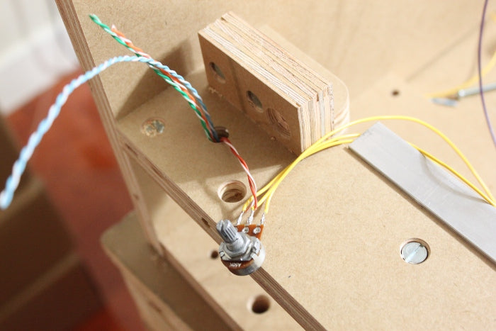
At this end of the ethernet cable, strip enough insulation so that enough if the wire will be exposed to connect to the potentiometer and to the breakout board. Solder the other end of the brown wire with white stripe from the LED panel to the 5k potentiometer left lead as shown with a wire that will connect to the GND terminal on the laser tube power supply. Solder the other end of the brown wire along with a wire that will connect to the IN terminal on the laser power supply to the middle lead of the 5k potentiometer. Solder the right lead of the 5k potentiometer to a wire that will connect to the VCC on the laser power supply.
29
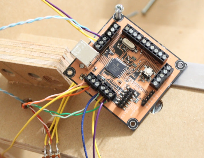
For USB breakout boards only: The following connections are explained from the image in a clockwise direction starting from the bottom right terminal that has a purple wire connected to it (CP=Step, CW=Direction): - First Terminal (CP Y-Axis) solid green from LED panel and a wire to the CP+ terminal of the Y-axis driver (39 inches of wire). - Next terminal (CW Y-Axis) wire to CW+ terminal on the Y-axis (39 inches of wire). - Next Terminal (GND Y-Axis) green/white from LED panel and wire to the CP- and CW- terminal on the X and Y drivers (36 inches of wire). - Next terminal (CW Z-Axis) solid orange from LED panel and a wire to the TH (H) terminal on the laser power supply. - Next terminal (GND Z-Axis) orange/white from LED panel. This GND does not need to be connected to the laser power supply GND terminal because the laser power supply provides its own signal ground. The next three terminals are shown in the incorrect three positions on the board. They should be on the next three labeled the X-Axis. - Next terminal (GND X-Axis) blue/white from the LED panel. This GND does not need to be connected to the X-Axis since the Y-Axix GND wire is jumped from the Y-Axis to the X-Axis driver to reduce the number and length of wires. - Next terminal (CW X-Axis) wire to the X-axis CW+ terminal (44 inches of wire). - Next terminal (CP X-Axis) solid blue and a wire to the CP+ terminal of the X-axis (44 inches of wire). Use the parallel breakout board diagram if you have the parallel breakout board. For the LED connections on the parallel breakout board: - The x axis LED will be connected to pin #2 and 5V - The y axis LED will be connected to pin #4 and 5V - The laser on/off LED is connected to pin #6 and 5V
30
Make sure the wire from the USB interface board's Y-Axis GND is connected to the CP- terminal of the Y-Axis driver then jumps to the CW- terminal on the Y-Axis driver then jumps to the CP- terminal of the X-Axis driver then finally jumps and terminates at the CW- terminal of the X-Axis stepper motor driver.
31

The two toggle switches are connected to the black (live) AC power wire that is split off into a Y configuration. Each side of the Y split is connected to each toggle switch. One switch connects back to the laser tube power supply at the other AC terminal to which the white wire is not connected. The other switch connects back to the CNC power supply at the L terminal. The wires that lead back to the CNC power supply is 42 inches and 36 inches to the laser power supply.
32
Connect the X-axis stepper motor to the X-axis stepper motor driver with the same configuration as the Y-Axis driver. Use a cable at 13 inches of length with 4 stranded conductors. At this point, you can test the electronics to make sure the stepping motors spin. If you are using the USB interface board, you will need the planet-cnc software. Only unlicensed version is necessary at this point since you are only testing the motors. Later, when the machine is complete, the license can be purchased to make the laser system fully functional. The parallel breakout board can be tested with either the mach3 or linuxcnc software or other software that you may prefer that can output to the parallel port (most cnc control software has this feature).
33
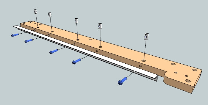
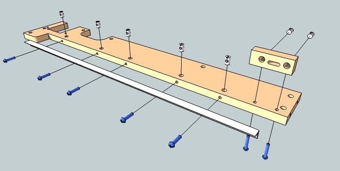
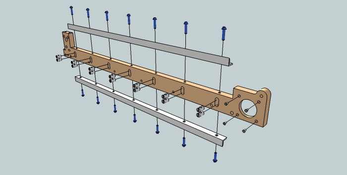
Attach the left-side Y-axis rail to the left-side Y-axis rail support as shown, using (5) cross-dowels and (5) ¼ x 1 inch screws.
34
Attach the left-side Y-axis drive rod support using (2) cross-dowels and (2) ¼” x 1-1/2” screws.
35
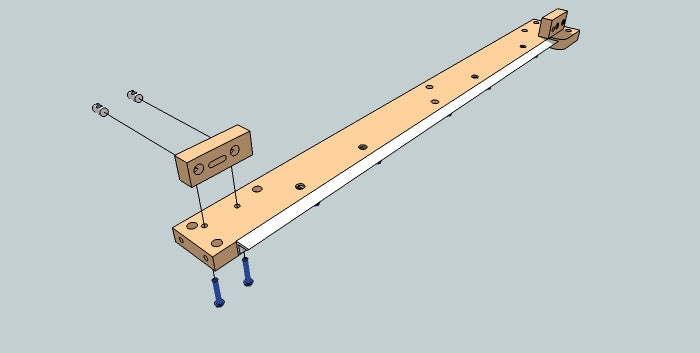
Attach the left-side Y-axis idler bearing support using (2) cross-dowels and (2) ¼” x 1.5” screws.
36
Attach the to the left-side Y-axis rail support to the front and back panels using (4) cross-dowels and (4) ¼” x 1.5” screws as shown.
37
Attach the right-side Y-axis rail to the right-side Y-axis rail support as shown, using (5) cross-dowels and (5) ¼” x 1” screws. Attach the right-side y-axis idler bearing support using (2) cross-dowels and (2) ¼” x 1.5” screws.
38
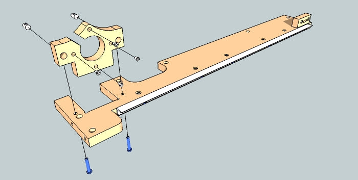
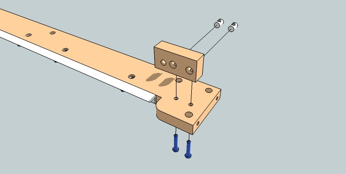
Insert (4) #8 nut inserts into the Y-axis motor mount. Attach the mount to the right-side Y-axis rail support using (2) cross-dowels and (2) ¼” x 1.5” screws.
39
Attach the to the right-side Y-axis rail support to the front and back panels using (4) cross-dowels and (4) ¼” x 1.5” screws as shown.
40
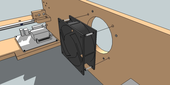
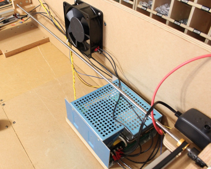
Attach the Vent Fan to the inside wall of the back panel as shown using (4) #8 1" screws. Be sure that the “Air Flow” arrow is pointing to the backside of the panel so that the air will be sent out of the machine. (Photo of airflow arrow)
41
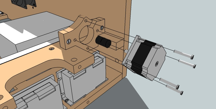
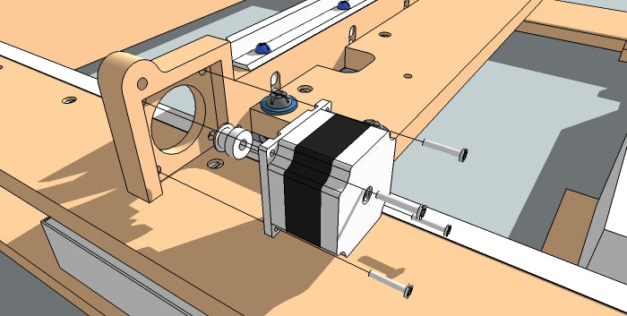
Place the rigid coupling around the motor shaft so that the end of the shaft is at the center of the coupling. Using a size 3/32 allen key, tighten two set screws to hold the coupling to the motor shaft. Be sure to orient the motor so that the wires are able to route beneath the rail support, then attach the motor to the Y-axis motor mount as shown, using (4) #8 x 1” screws.
42
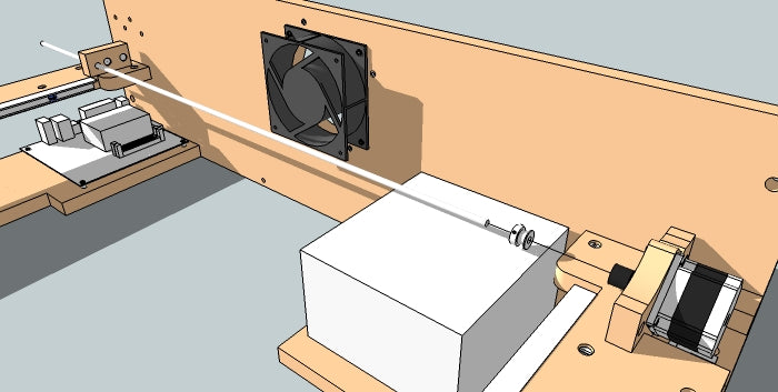
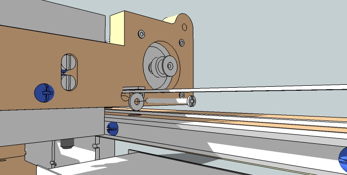
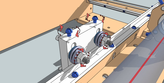
Slide the Y-axis drive rod through the left-side y-axis drive rod support. Slide on a Belt Pulley as shown and insert the rod into the rigid coupling until it nearly meets the motor shaft. Leave the sprocket set screws loose so you may adjust it later. Tighten the two remaining set screws on the coupling to secure the rod.
43
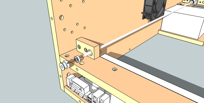
Slide a ¼” bearing and a Belt Pulley onto the other end of the rod. Leave the sprocket loose so you may adjust it later.
44

Insert two cross dowels and (2) ¼ x 1-1/2 inch screws into the left-side gantry bearing support (the smaller part with two slotted holes) to use as set screws for those two bearing assemblies. Assemble the (4) V-groove bearing assemblies onto the left and right gantry bearing supports. Each assembly in order is - (3/8 x 2 inch screw, 3/8 inch washer, wood part, 3/8 inch washer, 3/8 inch thin washer, V-groove bearing, 3/8 inch nut).
45
Join the left and right gantry bearing supports by attaching the gantry connector with (8) ¼” x 2” screws and (8) ¼” nuts as shown. Make sure to keep the screws and nuts loosely fastened at the slot locations.
46
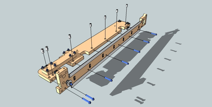
Attach the X-axis rails to the X-axis Rail Support, using (14) cross-dowels and (14) ¼” x 1” screws. Screw (4) #8 nut inserts into the rail support as shown.
47
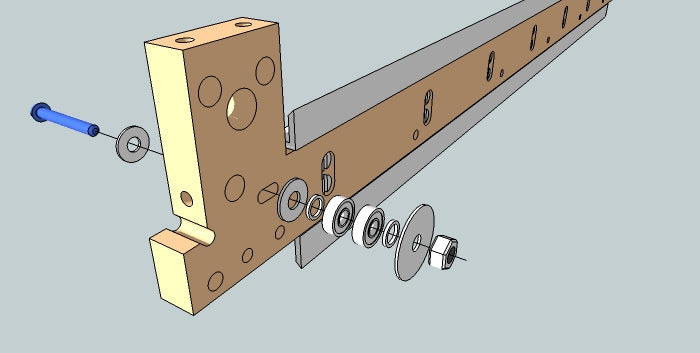
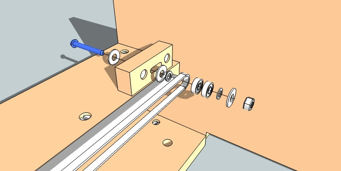
(This photo shows the front side of the X-axis Rail Support. ) Attach the X-axis Idler Bearing Assembly to the X-axis Rail Support. From the back side of the X-axis Rail Support, the assembly is – (¼ x 2 inch screw, ¼ inch washer, wood part, ¼ inch washer, ¼ inch thin washer ¼ inch bearing, ¼ inch bearing, ¼ inch thin washer, ¼ inch fender washer, ¼ inch nut).
48
Attach the gantry bearing support assembly to the X-axis Rail Support using (7) cross-dowels and (7) ¼” x 1.5” screws. Once the gantry assembly is fastened to the rail assembly, the screws and nuts that are loosely fastened to the slotted locations for the gantry assembly can be tightened at this time. Step number 29 can be done at this time if you wish. The motor may be easier to fasten to the gantry once this assembly is complete.
49

(Back-side view of gantry) Mount the gantry onto the Y-axis rails by first setting the right-side bearings onto the right-side rail, then lowering the left-side bearings into place.
50

Be sure the nuts in the bearing assemblies here are loose enough to adjust the position of the bearings. Tighten the set screws so that they press these left-side bearings onto the rail (tight enough to stay onto the rail without any wobble or ‘play’, but not so tight that they are not able to roll along the rail. They should roll smoothly without having to use much force to move the gantry). Then, tighten the nuts of the bearing assemblies to secure them into place.
51
Now, attach a Belt Pulley onto a motor, and mount this onto the X-axis Rail Support as shown, using (4) #8 x 1/2 inch screws (If no #8 1/2 inch screws are in the package, use #8 x 1 inch screws). The motor wires should be towards the right side of the machine, or top, not toward the inside of the machine or the bottom as the motor wires be get caught on another part of the machine during motion.
52
Insert one #8 1-1/2 inch screw into the hole shown with a #8 washer as Part 1 of securing the timing belt for the Y-Axis
53

Complete the fastening of the screw be adding a #8 nut and washer to the other side.
54
Attach the Y-Axis Belt Idler Bearing Assembly using one 1/4 x 2 inch screw, three 1/4 inch standard washers, two 1/4 inch small 1/4 inch washers, and one 1/4 inch nut. Wrap the belt around the bearing during this process. Repeat this step on the other side of the machine.
55
Fasten the other belt to the gantry using one #8 x 2 inch screw, nut and two washers.
56

Assemble the Nozzle Bearing Plate. Attach the (2) #8 nut inserts to the back of the plate (when looking at the back of the plate, these holes will be just to the right of center). Loosely attach the Nozzle to the other side of the plate using (2) #8 x 1 inch screws (Note: You may need to use #8 washers to shim the nozzle away from the plate). Attach the (4) V-groove bearing assemblies to the plate. The v-groove bearing assemblies consist of 3/8 x 2 inch screws, 3/8 inch washers, 3/8 inch thin washers v-groove bearing and 3/8 inch nut. The v-groove bearing adjustment screws consist of 1/4 x 1-1/2 inch screws and cross dowels.
57

For steps No. 35, 36, 37 and 38: Insert the belt into the Nozzle Bearing Plate, and insert the (2) #8 washers and (2) #8 x 1-1/2 inch screws to loosely hold the belt into place. Be sure that the X-axis idler bearing assembly is set to the farthest position to the right in its slot. Temporarily remove the nut and large washer from the bearing assembly. With the Nozzle Bearing Plate held up to the X-axis rails by hand (but the bearings not actually being on the rails), wrap the belt around the idler bearing assembly and the drive sprocket on the X-axis motor. Carefully pull the belt tight. Slide the belt off the idler bearing and secure the belt to the Nozzle Bearing Plate by attaching a #8 washer and nut to each of the #8 x 1-1/2 inch screws.
58

59

60

61
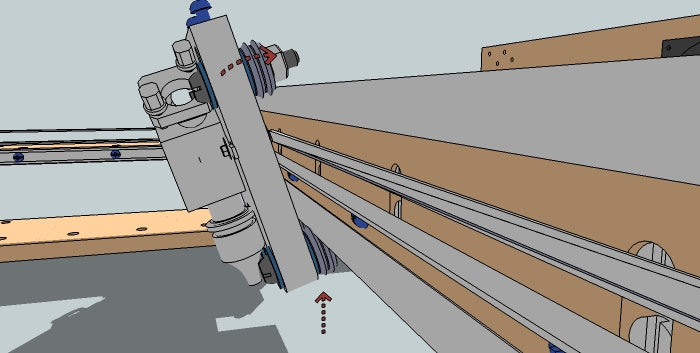
Loosen the top 2 bearing assemblies on the Nozzle Bearing Plate. Attach the plate to the X-axis rails by first pressing the bottom two bearings up against the lower rail, then swinging the top two bearings into place onto the upper rail. Tighten the two set screws and then the nuts on the bearing assemblies.
62
Be very careful not to add too much force against the rail. Only very light force is needed to press the bearings against the rail
63

Once again, slide the belt around the drive sprocket and the bearing assembly. Then, loosely re-attach the large ¼” washer and ¼” nut to the bearing assembly. Push the bearing assembly to the left to tighten the belt, then secure it into place by tightening the nut.
64
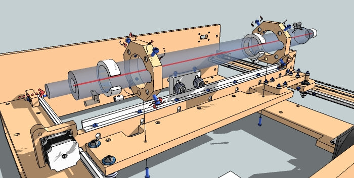
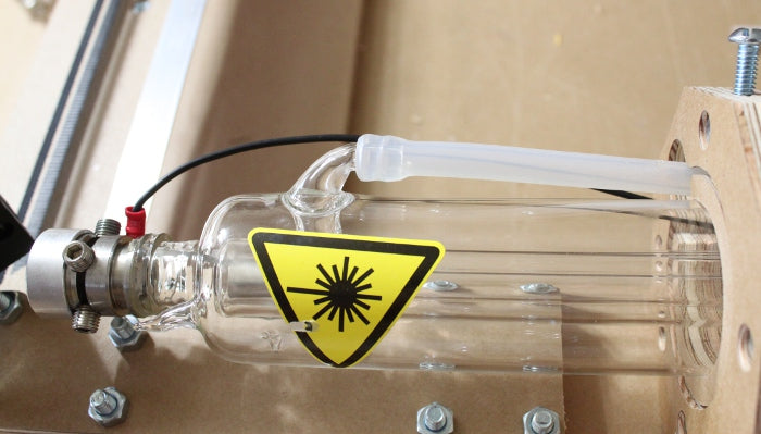
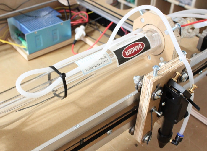
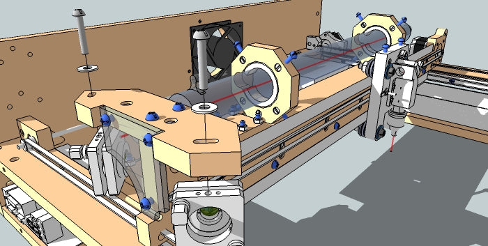
Carefully slide the c-shaped Tube Rings onto the laser tube as shown. Slide this assembly into the Tube Supports, then mount this to the gantry using (2) cross-dowels and (2) ¼” x 1.5” screws. Loosely secure the tube inside the Tube Supports using (8) cross-dowels and (8) ¼” x 1.5” screws. These screws will be used to partially adjust the beam during alignment later.
65
Attach the Mirror Mount to the gantry by first attaching the wood piece using (2) cross-dowels and (2) ¼” x 1.5” screws. Then, attach the acrylic piece using (3) cross-dowels and (3) ¼” x 1” screws. Use caution not to over-tighten the acrylic, as it may crack with too much force.
66
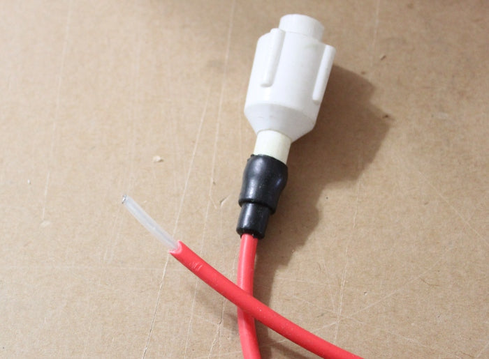
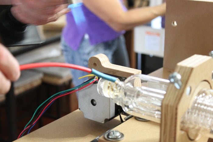
Using the extension cable as shown, strip the outer insulation from the high tension line exposing the inner clear insulation. This inner insulation is difficult to remove with a standard stripping tool.
67
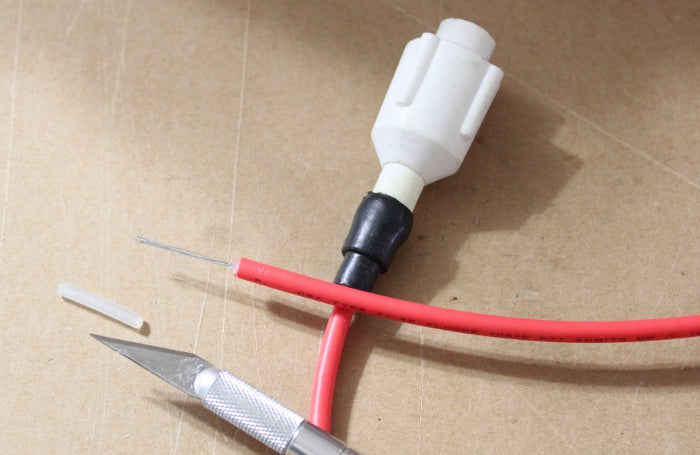
Carefully remove the inner clear insulation form the high tension line using a sharp blade or a specialized stripping tool for this purpose.
68
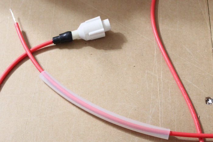
Slide on about 4 inches of silicone tubing that has a 1/8 inch inside diameter (the larger of the two that is supplied in the kit. This will serve as strain relief for the high tension line. !Important! Then add a heat shrink tubing to the high tension line.
69
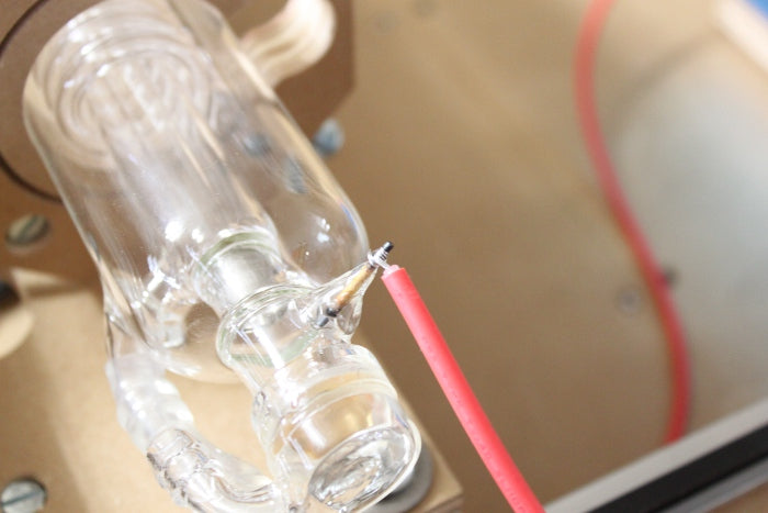
Wrap the exposed stranded wires from the end of the high tension line around the tungsten lead at the back of the laser tube.
70
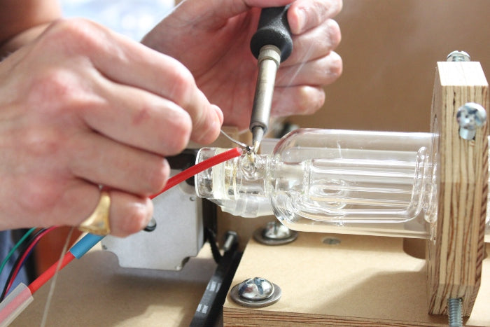
Solder the wrapped stranded wire from the high tension line to the tungsten lead.
71
Take the heat shrink tubing and slide it around the soldered connection and shrink the tubing using a heat source such as a lighter.
72
Slide the silicone tubing over the soldered and heat shrunk connection as far as it will go.
73

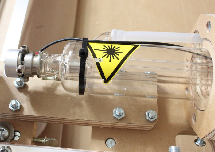
Zip-Tie the wire connection assembly around the tube as shown in the image. Make sure the connection is not under any stress during ad after this part of the process. This will provide strain relief for the connection.
74
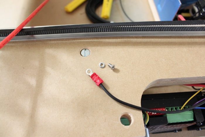
Crimp a small ring terminal to the end of a 68 inch flexible 18 gauge or larger wire. Remove the small screw from the other end of the laser tube. A very small split washer will also be used in the connection of the return line.
75
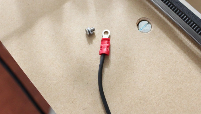
Put the split washer on the screw as shown and then add the ring terminal to the screw. Refasten the screw to the laser tube front snuggly.
76
Connect the return line of the laser tube to the power supply to the terminal at the far right. Connect the air pump to the power supply. There are two wires coming from the air pump. One with white letter writing along the length of the wire. This is the live, or black side and the other side is the neutral side. Make sure that these wire are connected to the AC AC terminals corresponding to where the neutral wire and live wire is connected on the terminals from the previous power connection step.
77
Connect the fan to the laser power supply using two wires. These wires will go to the two AC terminals on the power supply.
78
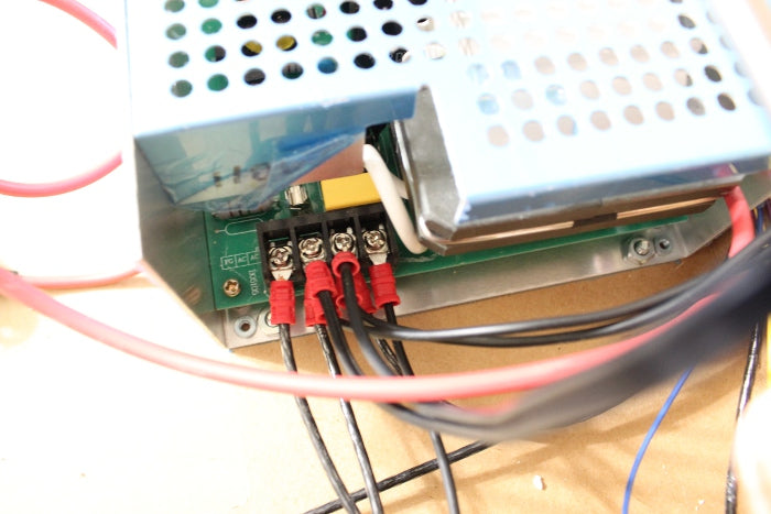
This is a close up of all the connections on the power supply. The first terminal, on the left, is the ground wire. The second and third terminals are the AC terminals and contain the power wires, air pump power wires and fan power wires. The forth terminal is for the return laser tube line.
79
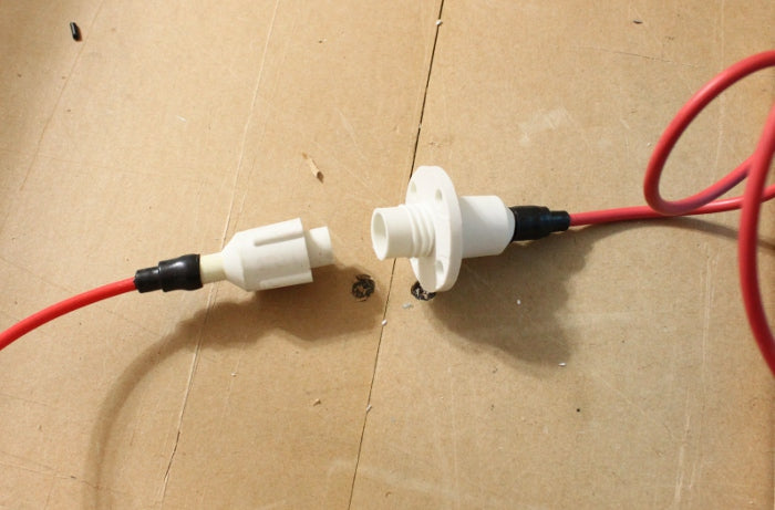
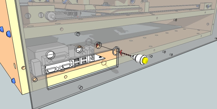
Connect the extension of the high tension line to the connector from the power supply. Route the extension from the tube through the small opening on the outer edge of the rail support and under the rail support to the power supply high tension line.
80
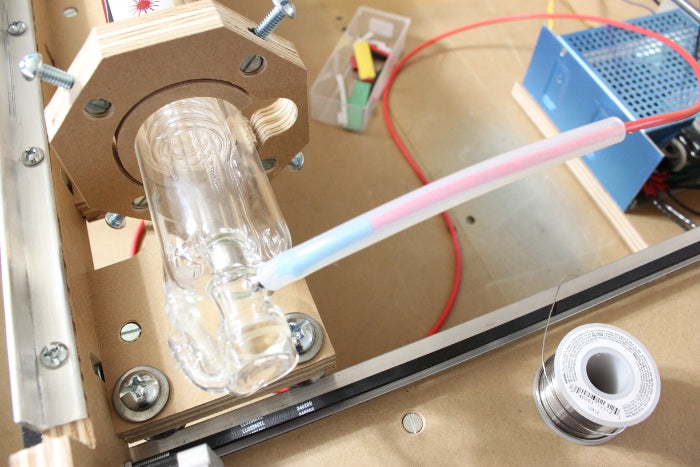
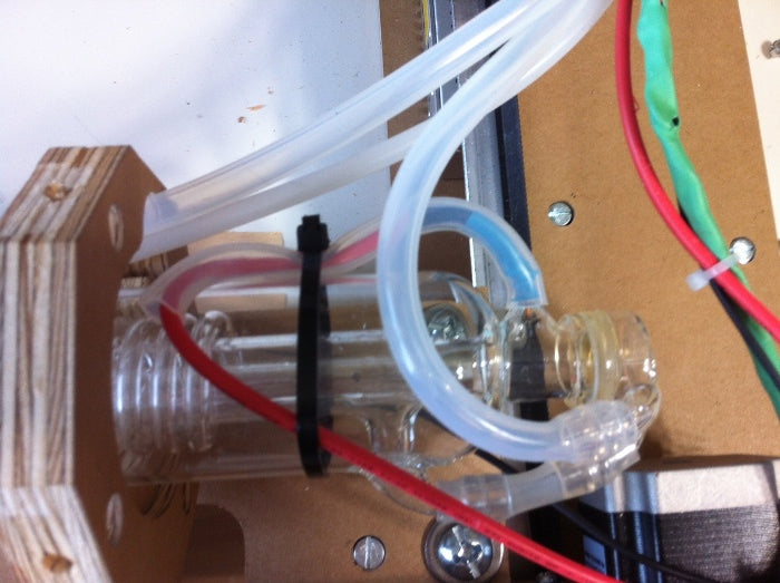
Install the silicone tube to the laser tube inlet. This will take some finesse and patience.
81
Zip-Tie the laser tube return line to serve as a strain relief as shown in the image.
82
Install the silicone tube to the laser tube outlet. This will take some finesse and patience.
83

Take the blue part of the air inlet fitting and slide this part onto the 1/16 inch inside diameter silicone tube as shown in the image. It is difficult to remove the blue part from the fitting. The silicone tube should stick out from the blue part as shown in the image so it will be caught by the internal catch inside of the fitting.
84
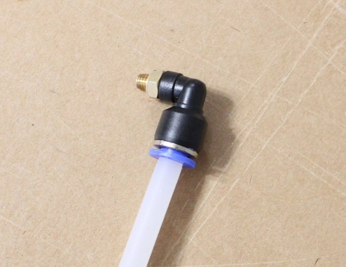
Insert the tube and blue part into the nozzle sir inlet fitting. Press firmly so the blue part snaps into place.
85
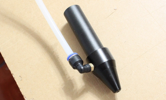
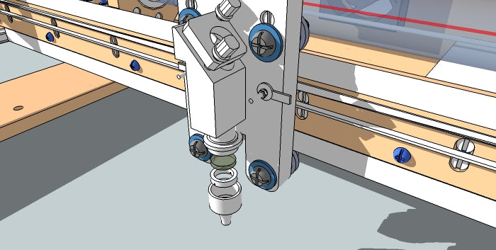
Remove the nozzle assembly from the laser head assembly using the tightening screw to adjust the height of the nozzle. Fasten the air inlet fitting to the nozzle as shown.
86
Route the other end of the silicone tubing to the air pump. Use the suggested routing of the tube to allow for full travel of the head and so the tube does not get caught on other parts of the machine. Air is pumped into the nozzle to provide a positive air pressure in the nozzle cavity so debris does not enter the nozzle. The air is pumped fast enough to extinguish small flare-ups during engraving and cutting. Re-install the nozzle assembly to the laser head assembly.
87
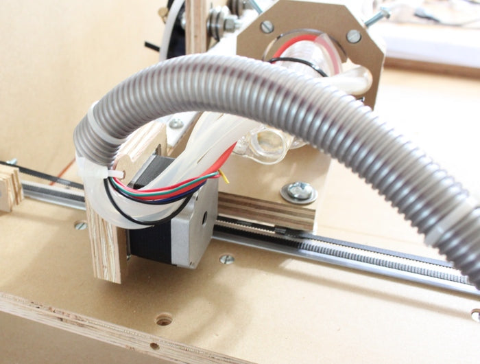
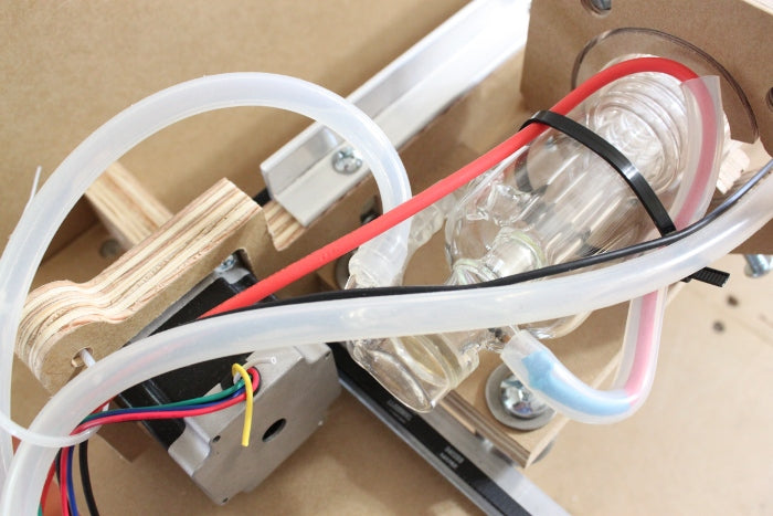
To provide for adequate wire and tube management, use a zip-tie and combine all of the wires and tubes at the hole just above the motor as shown. It's best to have the wires and tubes pointing upwards. Make sure not to kink the silicone tubing to allow full water flow. Use a flexible conduit as shown. This assists the wires and tubes to not get caught on other parts of the machine during use.
88
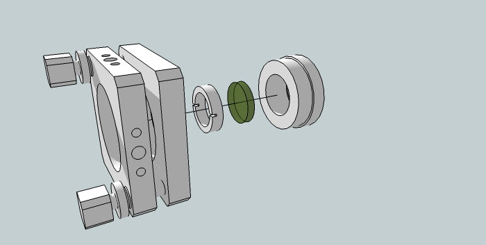
Remove the parts of the mirror mount that are used to secure the mirror, insert the mirror and re-install the mirror set screw and main mirror holder. Do this for both mirror mounts. For all lens and mirror mounting, use a soft lens cloth when handling the lens and mirrors. When installing the mirror, you will see a gold side and a flat, or silver side. The gold side will be the reflecting side, so make sure the gold side is facing out.
89
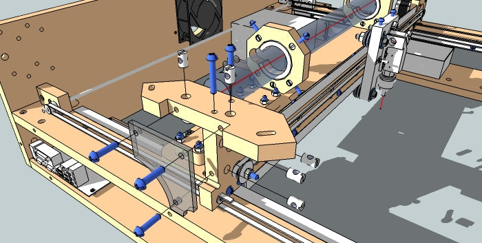
Install the mirror mounts to the main mirror mount on the gantry using two M6 screws and washers.
90
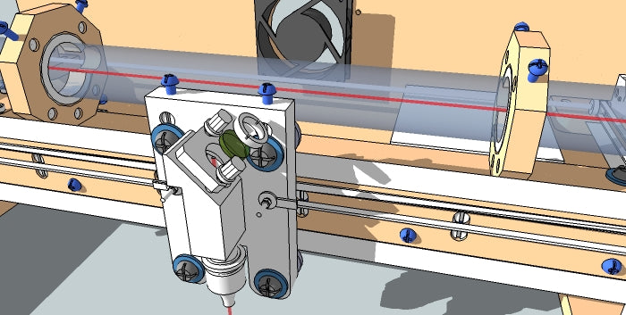
Install the final mirror at the top of the nozzle by removing the mirror set screw. Insert the mirror and re-insert the set screw. Make sure the mirror is oriented facing the beam.
91
Insert the focus lens into the nozzle be removing the nozzle end and removing the lens set screws. Reattach the setscrew and nozzle end.
92
Fasten the Parallel or USB breakout board to the back panel as shown using (4) plastic spacers, and (4) #8 x 1” screws.
93
Attach the PC Power Button to the acrylic Left Panel as shown. This step is only valid if the computer motherboard is installed within the machine.
94
Attach the Left Panel to the left-side Y-axis Rail Support using (3) cross-dowels and (3) ¼” x 1” screws.
95
Attach the Left Panel to the left-side base using (3) cross-dowels and (3) ¼” x 1” screws.
96

Attach the two Toggle Switches to the Left Panel as shown. These will be used to power the CNC motion electronics and the Laser Tube independently.
97

If the computer option was chosen, attach the Hard Drive to the Left panel using (3) #8 washers and (3) #6 x 3/8” screws as shown.
98

Attach the Left Panel to the Back Panel using (2) cross-dowels and (2) ¼” x 1” screws.
99

Attach the Left Panel to the Front Panel using (2) cross-dowels and (2) ¼” x 1” screws.
100
The high tension line from the power supply (red line) is soldered to the tungsten lead at the back end of the laser tube. Add heat shrink and some silicone tubing (1/4 inch ID) to the wire before soldering to the tungsten lead. Solder the wire to the tungsten lead. Slide the heat shrink around the tungsten lead and the wire and heat to shrink the heat shrink tubing. Slide the silicone tubing around all of the heat shrink tubing. Tie the tubing with a zip tie or high quality tape.
101

Attach the two Coolant Hose Connectors to the acrylic Right Panel as shown. The fittings may not appear as shown and may appear having a right angle. Errata: These connectors may not be included. Route the hoses through the holes in the Plexiglas and omit the connectors.
102

Attach the Right Panel to the right-side Y-axis Rail Support using (3) cross-dowels and (3) ¼” x 1” screws.
103

Attach the Right Panel to the right-side base using (3) cross-dowels and (3) ¼” x 1” screws.
104

Attach the Right Panel to the Front Panel using (2) cross-dowels and (2) ¼” x 1” screws.
105

Attach the Right Panel to the Back Panel using (2) cross-dowels and (2) ¼” x 1” screws.
106

Insert (12) #8 nut inserts into the Hinge Plate.
107

Attach the Hinge Plate to the Left Panel using (2) cross-dowels and (2) ¼” x 1” screws.
108

Attach the Hinge Plate to the Right Panel using (2) cross-dowels and (2) ¼” x 1” screws.
109

Insert (12) #8 nut inserts into the Rear Access Lid as shown.
110

Insert (12) #8 nut inserts into the Front Access Lid as shown.
111

Attach the small acrylic window to the Rear Access Lid using (6) #8 x 3/8” screws.
112

Attach the large acrylic window to the Rear Access Lid using (6) #8 x 3/8” screws.
113

Connect the two Access Lids to the Hinge Plate using (4) hinges and (24) #8 x 3/4" screws. If the Access Lids do not align with the sides of the machine, loosen the screws that connect the left and right panel to the hinge plate, make your adjustment, then tighten them to secure into place.
114
Tests have been made to find the measurement required for the optimum focal length (the length that the optics needed to be from the surface of the material being marked by the laser). We fabricated a gauge to have this focal length be set for every job. This is the first test and setup of the machine. In this test, we aligned the 40W CO2 laser tube with the three mirrors. This is the most critical and dangerous step. Because of this danger, we decided to use couple techniques. The first technique required a camera facing up into the nozzle, pointing at the last mirror. If the firing end of the laser tube could be seen in the camera, then the mirrors were generally aligned, but we found that this is not a promising technique since the tube itself would need to be properly aligned and not just the firing end of the tube. The other method is to use a laser pointer, but the laser pointer must point exactly though the center of both laser tube mounts to ensure that the mounts of the laser tube could be adjusted correctly. Unfortunately, no laser pointer that I know of points straight relative to the body of the laser pointer. The answer to this problem is to fabricate round objects with a diameter matching the tubes diameter with a tiny hole in the center that will allow the laser pointer light to pass. The laser pointer would, of course, need to be held in a steady position so the mirrors can be aligned.
115
The second test was to determine the performance of the linear motion, vibration, rigidity and quality of the structure and markings. We tested two velocities and two flammable materials. We chose flammable materials to see how well our air system performed. The velocities were tested to determine the quality of the markings.
116
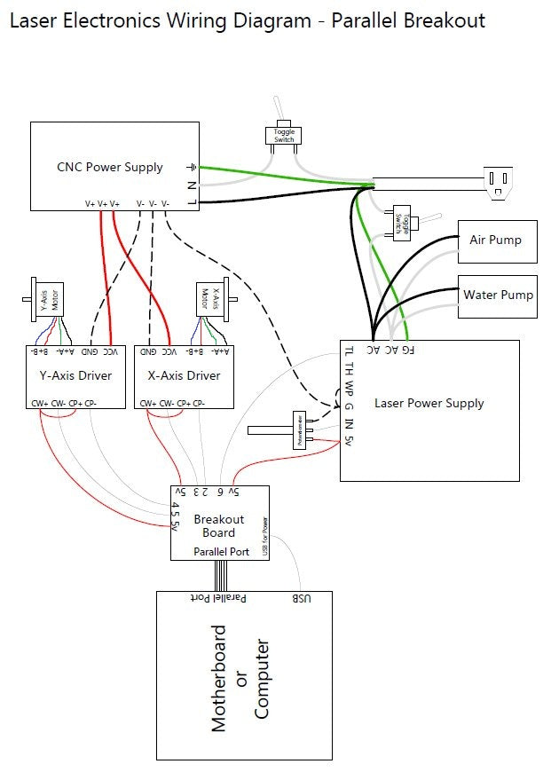
Laser wiring diagram for the parallel breakout.
117
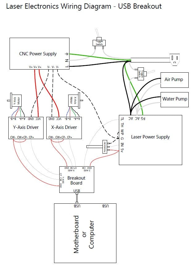
Laser wiring diagram for the USB breakout. Wiring Diagram Errata ** the z-axis line from CW should be connected to the TH terminal on the laser power supply. The z-axis gnd should be connected to the gnd terminal on the laser power supply. Disregard the diagram for these two points.
118
Software setup. If you have the parallel port breakout board, either Mach3 (windows) or Linuxcnc or EMC (Linux) can be used to control the laser cutter motion. If our USB breakout board is used, the planet-cnc software (windows) is required to run the machine. Determining the steps per inch: (steps) / (inch) = (Motor effective steps per revolution) / (pitch circumference) = ( (motor steps per revolution) * (microsteps) ) / (pulley pitch per tooth) * (number of teeth) = (200 * 16) / (0.08" * 20 teeth) = 3200 steps / 1.6 inches circumference = 2000 steps per inch If you wanted to use 8 microsteps: = (200 * 8) / (0.08" * 20 teeth) = 1600 steps / 1.6 inches circumference = 1000 steps per inch
119
Aligning the Laser Beam to travel from laser tube and exit successfully out of the nozzle. This process is intended only for the blackTooth laser cutter/engraver since the laser tube is mounted onto the gantry. This configuration of the laser tube mounted on the gantry enables the user to align the laser very easily and only the x axis travel is considered in the alignment rather than the x and y on traditional lasers making the alignment potentially challenging. How to adjust the individual mirrors: The first two mirrors have are held by a single M6 screw that can allow for rotation and the screw is in a slot so that the mirror can be moved side to side horizontally. All of the mirrors also contain two screws that can adjust the up and down angle of the mirror. With these adjustments, you have full control of the alignment of the laser beam. The tube can also be adjusted at the two mount locations. The tube should be centered within the mounts at first. First, use card stock to assist in alignment since the other materials, such as tape, may be harmful. Card stock is harder to ignite than paper. Thermal paper can also be used. Make sure the doors of the machine are closed during the firing of the laser. Put the card stock over first mirror (bend the card stock so that it can be placed over the top of the mirror mount and fold over the mirror. Initiate lasing on the first card stock repeatedly while adjusting the tube and the mirror until the center of the mirror is hit. Repeat for second mirror while adjusting the first mirror to get a good center hit on the second mirror. Repeat for third mirror, but have the the mirror as far as possible from the second mirror to align for the worst possible condition. Repeat with the mirror close to the second mirror to confirm that the beam is still aligned. Now, simply adjust the last mirror so that the beam exits the nozzle fully.
120
Motor driver setup dip switches: Follow the diagram of the to of the driver. The current (amps) should be set for 3.0 amps and the microstepping should be set for 8 or 16 depending on your preference from the formula on step number 73.
121
Software setup. The software that you use will depend on the interface used and the whether you are using Windows or Linux. First, if the interface is USB (and included in the kit, or provided by buildyourcnc.com) then the operating system must be Windows and the software to control the laser is - PlanetCNC USB software. Just click the link and the software will start automatically. If you have the parallel interface, you have the option of using the Windows or Linux (Ubuntu) operating system. If Windows is used, the instructions here will focus on Mach3. If Linux (Ubuntu) is used, then the Linuxcnc.org is recommended.
122
How does the laser operate with the control software? The control software will operate the x and y axes by sending pulses to each driver (through the interface) and send a direction signal to the x and y axes to change their directions. For parallel interfaces this is communicated by the pin number on the breakout board as shown on the wiring diagram on step 71. For instance, the x axis uses pins 2 and 3 to control the movement of the stepper motor. Pulses travel through pin 2 to move the axis and a high or low signal is sent through pin 3, high for one direction and low for the opposite direction. How does the laser fire? The control software, along with the laser power supply use the z-axis direction signal to turn on or off. If the z-axis moves down, the laser turns on, just as if it was a CNC machine's bit going down into the wood. When the z-axis moves up, then the laser turns off. Pin 6 on the breakout board is connected to the TL for this reason. The TL turns the laser on if the signal on that line is low.
123
Mach3 setup: In Mach3, the axes will be setup according to the pin numbers. First, the Mach3 Mill will be used in this scenario (when you first install Mach3, you will see a selection of Mill, Turn, or Plasma). To assign the pin numbers to the axis step and direction controls and confirm the parallel port, in Mach3, click on Config -> Ports and Pins. On this screen, verify that Port #1 is enabled and the port address is 0x378, which is the default if the parallel port is integrated on your motherboard. Click on the Motor Output Tab to access the configuration for the step and direction pins. Change the x axis step to 2 and direction to 3 and the direction and step will be low active, so make sure there is a green check mark on those cells. The step port and dir port should be 1. For the y axis, step is 4 and direction is 5 and the remaining is the same. For the z axis, the axis that will control the laser firing, the direction pin is 6 and the direction low active should be enabled. The step for the z axis should be 0. All three x, y and z should have the enabled checkmark. Setting the acceleration and velocity: click config -> Motor Tuning. A dialog box will appear that will allow you to change the steps per inch (or mm), acceleration and velocity for each axis. When making changes to each axis, make sure to click save changes prior to selecting another axis. The acceleration should be set to a value between 25-50. If you hear the motors stall at the beginning of the movement, then lower this number. The lower the acceleration, the slower the axis will ramp up to speed. You will want the acceleration as high as possible, but leave a good range from the highest possible value so there will not be a chance for a motor stall. The velocity field controls the speed of the axis when in a rapid movement, or when the laser is not on, going from the last lasing operation to the next lasing operation. You should be able to set this velocity anywhere between 150 to 500. As with acceleration, try to set the velocity as high as possible, but if the acceleration is high and he velocity is high, the laser may show a transient response (a springiness) because the axis is trying to stop too fast and the inertia of the axis forces it to bounce back and forth, at a corner, for instance. It is important to consider both feedrate (the velocity you set in your machining operations, or the speed it travels while the laser is on) and acceleration to avoid rounded corners. If the corners appear rounded when in a tool path operation for a geometric shape such as a triangle, increase the acceleration if possible, and/or decrease the feedrate.
124
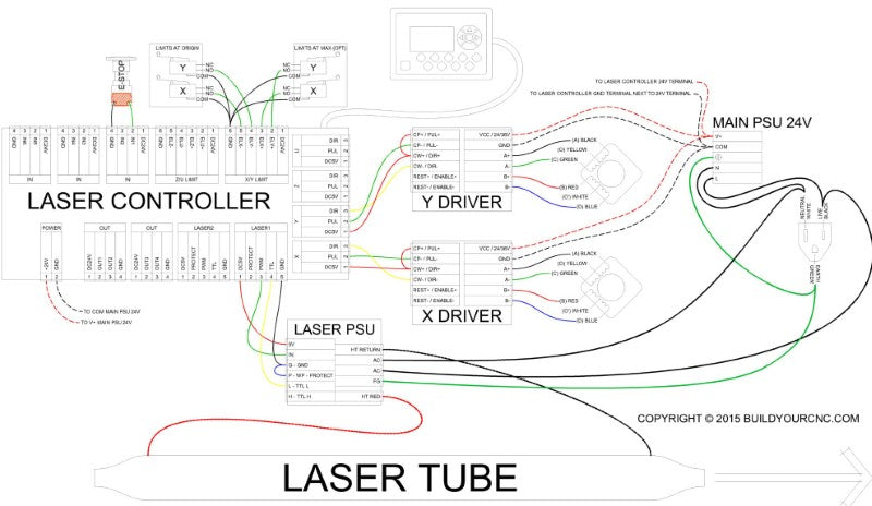
Wiring Diagram for Laser Control Unit Click here for exploded view.