Microcontroller - A Beginners Guide - Adding a Button to the Microcontroller and
Making it Do Something
A very simple and easy way to provide for human interaction with the microcontroller
is to insert a button into the circuit. We communicate with computers using two
main input devices: the mouse and the keyboard. A keyboard is nothing more than
a bunch of buttons laid-out to allow the user to input (ASCII) characters to the
computer. If you're scratching your head on the ASCII part, don't worry--it just
represents the code for each character.
By this point in our journey, you should have already
setup your computer with WINAVR (or AVR-GCC for Linux), and be able to
program your microcontroller. You should also have a circuit built with
an LED plugged into the microcontroller. You
also made the LED blink in the previous
tutorial.
 Adding
a button or switch to the circuit enables the microcontroller to receive human input.
Other forms of input for microcontrollers include (but are not limited to) a keyboard
or a mouse, buttons, switches, audio (through microphones), touch screen displays
and digitizers. There are of course many other devices that can provide input to
a microcontroller, but these may not all be activated by voluntary human action.
I place these other devices into the "sensing" category, as these devices typically
sense conditions or events and react accordingly. A few such examples include sensors
for tilt (accelerometers), detecting infrared energy or monitoring temperature.
Adding
a button or switch to the circuit enables the microcontroller to receive human input.
Other forms of input for microcontrollers include (but are not limited to) a keyboard
or a mouse, buttons, switches, audio (through microphones), touch screen displays
and digitizers. There are of course many other devices that can provide input to
a microcontroller, but these may not all be activated by voluntary human action.
I place these other devices into the "sensing" category, as these devices typically
sense conditions or events and react accordingly. A few such examples include sensors
for tilt (accelerometers), detecting infrared energy or monitoring temperature.
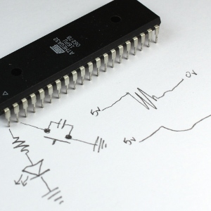
So, here's the skinny on buttons and mechanical switches: they're imperfect! The
two families of mechanics and electronics go together like the Montagues and Capulets.
That is, they don't! When you push a button, you might expect a clean response electronically.
Well, sorry to be the bearer of bad news, but the signal often bounces quite a bit
before it settles to its correct voltage level. In this image, I show this phenomenon.
If the voltage is set at 5 volts before the button is pressed and then goes to zero
volts when the button is pressed, there will be a "bouncing" effect of the voltage
between these two values. So then why don't all of our kitchen appliances or our
cars exhibit this problem?
As you should be able to see in the image, I have inserted a capacitor between the
two pins. This will smooth out the signal. The effect of this capacitor can be seen
on an oscilloscope, as demonstrated in the video. But if you don't have an oscilloscope
of your own, then you will just have to trust me. Another way we could alleviate
this problem is to add a time delay into the program, just after the microcontroller
senses the first button press event. However adding a discrete component to a circuit
to solve such an electronics problem, is often a better way than adding code to
cause a delay--as that code will introduce another potential source of a bug into
the program, and will also require more processor time to execute. In additional,
this code can also result in the development of other problems as the rest of the
code continues to execute.
But what value capacitor should we select? This will ultimately depend on how poorly
the button performs regarding this particular problem. Some buttons can display
a tremendous bouncing behavior, yet others will have very little. A low capacitor
value like 1.0nF (nanofarads) will react very quickly, with little or no effect
on the bouncing. Conversely, a higher capacitor value such as 220nF (which is still
pretty small in terms of capacitors) will provide a slow transition from the starting
to the ending voltage (i.e. 5v to 0v). The transition seen with a 220nF capacity
is still pretty fast in a real-world sense however, and thus can be used on poorly
performing buttons.
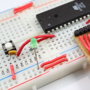 You
might have noticed by now that the breadboard has changed somewhat, to give the
circuit a cleaner look. The previous wires were too long, and the build environment
started getting messy as I added further components to the circuit. Therefore a
re-design of the breadboard was in order, so I snapped a second breadboard to the
end of the first. But you might be asking--why did I do this if there were sufficient
ties remaining at the other end? Well, I did it for neatness, and I also liked where
the microcontroller was positioned. You may be able to tell that I've aligned it
with the numbers so that I don't need to count pins all the time--I simply let the
breadboard numbering tell me where each pin is on the MCU. I also tied all of the
positive (+) rails on both boards together, and did the same to all of the negative
(-) rails as well. This will allow me to have VCC or GND close by, anywhere on the
breadboard.
You
might have noticed by now that the breadboard has changed somewhat, to give the
circuit a cleaner look. The previous wires were too long, and the build environment
started getting messy as I added further components to the circuit. Therefore a
re-design of the breadboard was in order, so I snapped a second breadboard to the
end of the first. But you might be asking--why did I do this if there were sufficient
ties remaining at the other end? Well, I did it for neatness, and I also liked where
the microcontroller was positioned. You may be able to tell that I've aligned it
with the numbers so that I don't need to count pins all the time--I simply let the
breadboard numbering tell me where each pin is on the MCU. I also tied all of the
positive (+) rails on both boards together, and did the same to all of the negative
(-) rails as well. This will allow me to have VCC or GND close by, anywhere on the
breadboard.
So then, how do we program the ATmega32 microcontroller (or other MCU that you may
be applying to this experiment) to make use of the new button? Well it's really
quite straightforward! We only have to add two initializing lines just prior to
the infinite loop, and a single condition block within the loop. The two initialization
lines added before the loop include one statement to set PINB1 for input by assigning
it a "0" like this:
DDRB &= ~(1 << PINB1);
We will also set pin B1 "high," meaning the pin will read 5 volts until the button
is pressed; at which time the pin will read zero volts. To set the pin at a high
voltage of 5 volts, we add this line of code:
PORTB |= 1 << PINB1;
Within the program, there must be a decision: a decision to run some code when the
button is pressed, or run some other code if the button is not pressed. This task
is in the form of a conditional statement called an "if else" statement. It does
EXACTLY what is says. Just like the English equivalent... if (the button is
pressed), jump up and down, else stand on your head.
the action "jump up and down" will happen while the button is pressed. But while
the button is not pressed, the other action "stand on your head" will happen. The
if statement code:
if (bit_is_clear(PINB, 1))
specifies a test for a condition specified inside the parentheses. The name "bit_is_clear"
represents a function that takes two arguments. In this case the first argument
is PINB, which describes the set of pins we are specifying. The second argument
represents which pin we are checking, and in this case we are concerned with pin
#1 in the set.
You might be wondering what sorts of things can we put into the code block controlled
by the "if" condition? That all depends on what you want your program (and circuit)
to do. In this case, as a way to show that this button does something and works,
I have the LED blinking slowly (every 100 ms) while the button is not pressed, and
blinking faster (every 10ms) while pressed.
Here are the changes made to the previous LED blinking program:
#include <avr/io.h>
#include <util/delay.h>
int main(void)
{
DDRB |= 1 << PINB0;
DDRB &= ~(1 << PINB1);
PORTB |= 1 << PINB1;
while (1)
{
PORTB ^= 1 << PINB0;
if (bit_is_clear(PINB, 1))
{
_delay_ms(10); //Fast
}
else
{
_delay_ms(100); //Slow, from previous
}
}
}
That is it!! There is very little programming required to use a button, LED and
make things blink!