Communicating and Controlling the Dynamixel Digital Servo AX-12+ and AX-18A by Robotix
The digital servos from Dynamixel are high quality servos with control specifications such as high torque, constant rotation,
1024 steps of rotational resolution and even control with respect to degree of compliance in controlling position. Feedback
is also possible with these servos for changes in internal temperature, changes in supply voltage, angular position,
angulat velocity and load torque with the possibility of automatic control of these feedback parameters when they pass a
threshold of your choosing.
The benefit of using digital servos over the conventional analog servos is that you can control upto 254 digital servos using
only one microcontroller. Analog servos consume the resources from the microcontroller, and to get many servos to work on a
single microcontroller, the PWM (Pulse width Modulation) signal must be generated manually on the pins of the microcontroller,
also referred to as big banged. Additionally, you are restricted to the number of free pins on the microcontroller for the
number of servos that can be used.
For the experiments that I will be doing, two different models of digital servos will be used, the AX-12+ and the AX-18A,
the latter being the later developed version. The AX-12+ has a lower speed at 59 rpm where the AX-18A hhas a speed of 97 RPM.
Both servos have very high stall torque for their size at 210 oz-in (1.5 Nm) for the AX-12+ and 254 oz-in (1.8 Nm) for the
AX-18A. All of these specification assume a 12.0 volt power, but they will also accept as low as 9.0 volt, but the torque and
speed will be reduced. They both follow the same procedure for communication and control.
The communication hardware and configuration:
 We will use the ATMega microcontroller to control a Dynamixel digital servo by Robotis using UART. The digital servos allow a
single communication wire to serve as transmit and receive on the same line and with speeds up to 1 million bits per second
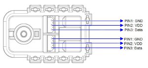
(BPS). As can be seen in the illustration, each servo contains two connectors. Each connector has the following pins:
Pin 1 - GND, Pin 2 - VDD and Pin 3 - Data. The GND is connected to the common ground of the circuit. The VDD is the servo
power voltage, not the signal voltage that is connected to the microcontroller, unless you want a very underpowered servo.
We will use the ATMega microcontroller to control a Dynamixel digital servo by Robotis using UART. The digital servos allow a
single communication wire to serve as transmit and receive on the same line and with speeds up to 1 million bits per second
(BPS). As can be seen in the illustration, each servo contains two connectors. Each connector has the following pins:
Pin 1 - GND, Pin 2 - VDD and Pin 3 - Data. The GND is connected to the common ground of the circuit. The VDD is the servo
power voltage, not the signal voltage that is connected to the microcontroller, unless you want a very underpowered servo.
Our microcontroller will be configured to communicate at half duplex UART, where only one data line is used. Throughout this
experimentation process, I would recommend using a microcontroller that has two UARTs on the chip so we can use one for the
communication with the servos, and the other can be use to connect to the computer. This is not absolutely necessary, since
you may want to have all the input at the microcontroller and not the computer. An LCD is used as well so we can view some
of the things that are going on with the servos.
We will also need to use two other chips: the 74HC126 (3 State Quad Buffer Line Driver) and the 74HC04 (Hex Inverter). The
74HC126 will connect to the TXD and RXD of the microcontroller and will also be connected to another pin on the
microcontroller that will determine direction of communication (receiving or transmitting, a 1 or 0). The 74HC04 will
provide the inverted signal to change the state of the 74HC126 line driver. When the direction pin in high, or 1, then we
will be transmitting to the servo(s). When the direction pin in low, or 0, then we will be listening to the servo(s).
Generally, the state of the direction pin will be 0, or listening most of the time (as default). It will only be set to high when the we
are ready to transmit data then immediately set back to low, or 0.
So, where shall we put the direction pin? Let's assume we will be using the 324P, or the 644A. They both have the same pin
configuration. I don't want to use the Port A because I will surely use that for the analog to digital converter for sensors,
like accelerometers and gyros, or range finders. Port C will most likely be used for the LCD data, so that is ruled out.
Port B or D is a good option. The LCD has some control lines that only use about 3 pins, so I will use that port as well.
Port D contains all of the UARTs which is pin 0 to pin 3 (4 pins: RXD0, TXD0, RXD1 and TXD1). We have 4 remaining on Port D,
so that should work well. Port B is lightly consumed by the SPI pins, and we will need those for programing. If we need
buttons, or LEDs, we still have 5 pins remaining.If we want more pins, then we will have two options, either get another
microcontroller and use it for functions like LCD and such. Otherwise, SMD would be the only other way where I would use the
ATMega 1280 or 2560, which has 100 pins or the ATMega 1281 or 2561 which has 64 pins. Those could be soldered to an SMD board
that exposes pins to plug into the breadboard, or a PCB would need to be fabricated, but I like to stay away from that until
I know I have a good circuit and everything works well.
The communication dataframe and packets:
A single command packet an contain many commands, such as position, velocity, compliance and torque.