Microcontroller - A Beginners Guide - Writing Our first LCD Program
Now that we know almost all that we need to know about interfacing the LCD to the
microcontroller, we can jump right into programming. We know the sequence that we
need to control the pins of the LCD from the previous tutorial. Lets list the sequence
so we can understand how to create the program.
If we want to send a command or a character to the LCD, we must first check to see
if the LCD is busy or not. If not, then it is ok to send the command or character.
Let take a look at the sequence of instructions we need to use to check the busy
status. Also, consider peeking at the LCD processor's
datasheet. This has all of the georgous information and specifications that
you could ever want to know about LCD's. Lost? Count on me to help decipher this
information these tutorials.
(1) Set the microcontroller port data direction to input. Let's call this DDR port
as DataDir
(2) Set the pin connected to the LCD RW to ON (read mode)
(3) Set the pin connected to the LCD RS to OFF (command mode)
(4) Turn the enable on, then off after a tiny delay.
(5) Read the D7 pin to determine if it is a 1 or a 0.
(6) Do numbers 4 and 5 until the D7 is 0 (meaning that it is not busy).
The above instructions would be contained in its own sub routine. We could call
it something like Check_If_The_LCD_Is_Busy. It might look like this:
void CheckIfBusy()
{
DDRB = 0b00000000; //Put PortB in Input (read) Mode
PORTD &= ~(1<<2); //Turn on Mr. LCD's Command Mode (RS off)
PORTD |= (1<<7); //Set Mr. LCD to Read (RW on)
while (PORTB >= 0x80); //D7 pin will be a "1" with any number above 0x80 (that's
hex)
{
BlinkLight(); // this is just another routine to turn the enable on and off
}
DDRB = 0xFF; //Set portB as output
}
That BlinkLight() command is just a routine to turn on the enable and then turn
it back off. The LCD needs this to be able to perform the action that it needs to.
It's like giving Mr. LCD a kick to do his job! the code might look like this:
void BlinkLight()
{
PORTD |= (1<<5); //Turn Enable on so Mr. LCD can function
asm volatile ("nop");
asm volatile ("nop");
PORTD &= ~(1<<5); //turn off Enable so Mr. LCD can Concentrate
}
Ok, here is a quick quiz... Can you tell me what pin the Enable is connected to
on the microcontroller? Don't worry about the port for now, just the pin.
Here are some new commands: asm, volatile and "nop". The "nop" is actually a command
within the language of assembly (aka assembler). This just allows the microcontroller
to wait some nanoseconds. According to the datasheet, the Enable must be kept on
for about 500 ns (nanoseconds).
So, now we have enough ammunition in our arsenal to start creating the code for
sending a command, or sending a character to the LCD display. The two are actually
very similar. First we check to make sure the LCD is not busy. We are setting the
RS to off to send a command, and on to send a character. The port must have the
output direction and the port must be equal to the approprate character, or command.
Then the RW read/write would be off for write mode. The LCD can be flashed with
the enable (the BlinkLight command). The LCD then magically performs the action
(displays the character, or follows your direction -"command"). Here is what this
code may look like:
void SendCommand(unsigned char command)
{
CheckIfBusy();
PORTB = command;
PORTD &= ~((1<<2)|(1<<2)); //turn off RS (command mode) and RW (write
mode)
BlinkLight();
DDRB = 0;
}
void SendCharacter(unsigned char character)
{
CheckIfBusy();
PORTB = character;
PORTD &= ~(1<<7); //turn off RW (write mode)
PORTD |= (1<<2); //turn on RS (character display mode)
BlinkLight();
DDRB = 0;
}
You are now saying, why aren't you setting the data direction for the port. Well,
the data direction for port B will always be in output mode unless it is check to
see if the LCD is busy. So, within the CheckIfBusy() routine, I first make the port
input, then at the end of the CheckIfBusy() routine, I put it back to output.
Wouldn't it be a pain in the #%^ if you needed to change the locations of the wires
from the LCD to the microcontroller if you decided to, say, change the port. This
is totally possible becuase the ports have other functions as well. You would need
to go through almost each line of code and change the pin and port specifications.
An easier way would be to asign these pins, ports and even port direction at the
beginning of the program. We do this with the "#define" statement. It's pretty self
explanitory just by looking at the program. Essentially, you are creating a proxy
(proxy... an evil clone, but with a different name... think about it, in the year
2245, you wouldn't name your clone with the same name? Would you?) for these numbers
and port designations and populating the program with these proxies instead. Here
is the program at this stage having the ability to send commands and characters
to the LCD.
#include <avr/io.h>
#include <util/delay.h>
#define MrLCDsCrib PORTB
#define DataDir_MrLCDsCrib DDRB
#define MrLCDsControl PORTD
#define DataDir_MrLCDsControl DDRD
#define LightSwitch 5
#define ReadWrite 7
#define BiPolarMood 2
void Check_IF_MrLCD_isBusy(void);
void Peek_A_Boo(void);
void Send_A_Command(unsigned char command);
void Send_A_Character(unsigned char character);
void Send_A_String(char *string);
int main(void)
{
DataDir_MrLCDsControl |= 1<<LightSwitch | 1<<ReadWrite | 1<<BiPolarMood;
_delay_ms(15);
Send_A_Command(0x01); //Clear Screen 0x01 = 00000001
_delay_ms(2);
Send_A_Command(0x38);
_delay_us(50);
Send_A_Command(0b00001110);
_delay_us(50);
Send_A_Character(0x4E); //N
Send_A_Character(0x65); //e
Send_A_Character(0x77); //w
Send_A_Character(0x62); //b
Send_A_Character(0x69); //i
Send_A_Character(0x65); //e
Send_A_Character(0x48); //H
Send_A_Character(0x61); //a
Send_A_Character(0x63); //c
Send_A_Character(0x6B); //k
Send_A_Character(0x2E); //.
Send_A_Character(0x63); //c
Send_A_Character(0x6F); //o
Send_A_Character(0x6D); //m
Send_A_String("Patrick");
while(1)
{
}
}
void Check_IF_MrLCD_isBusy()
{
DataDir_MrLCDsCrib = 0;
MrLCDsControl |= 1<<ReadWrite;
MrLCDsControl &= ~1<<BiPolarMood;
while (MrLCDsCrib >= 0x80)
{
Peek_A_Boo();
}
DataDir_MrLCDsCrib = 0xFF; //0xFF means 0b11111111
}
void Peek_A_Boo()
{
MrLCDsControl |= 1<<LightSwitch;
asm volatile ("nop");
asm volatile ("nop");
MrLCDsControl &= ~1<<LightSwitch;
}
void Send_A_Command(unsigned char command)
{
Check_IF_MrLCD_isBusy();
MrLCDsCrib = command;
MrLCDsControl &= ~ ((1<<ReadWrite)|(1<<BiPolarMood));
Peek_A_Boo();
MrLCDsCrib = 0;
}
void Send_A_Character(unsigned char character)
{
Check_IF_MrLCD_isBusy();
MrLCDsCrib = character;
MrLCDsControl &= ~ (1<<ReadWrite);
MrLCDsControl |= 1<<BiPolarMood;
Peek_A_Boo();
MrLCDsCrib = 0;
}
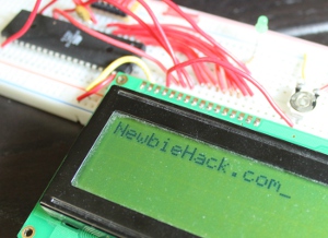 Here
is the result of the above program:
Here
is the result of the above program:
So you actually scrolled all the way down to the bottom of this page and actually
WANT MORE! I'm so excited and would refer you to my
next tutorial on adding string functionality to this LCD tutorial. If, on
the other hand, you are completely lost, you can go to the
previous tutorial to know more about the inner guts of the LCD, or you could
just
start from the beginning.