Microcontrollers - Creating an SPI Interface from the Programmer to the Microcontroller
to Make Transferring More Convenient
 So, at
this point, you should be familiar with the concept of the microcontroller (MCU).
You should also have an appreciation for the general uses of the microcontroller.
You have a basic understanding of the pin assignment and the Ports. And, hopefully,
you are excited with what a microcontroller can do, like sensing and controlling
the environment. Finally, you know that we will get into the programming side of
things--given the title of this page, and the fact that we touched on it in the
introduction).
So, at
this point, you should be familiar with the concept of the microcontroller (MCU).
You should also have an appreciation for the general uses of the microcontroller.
You have a basic understanding of the pin assignment and the Ports. And, hopefully,
you are excited with what a microcontroller can do, like sensing and controlling
the environment. Finally, you know that we will get into the programming side of
things--given the title of this page, and the fact that we touched on it in the
introduction).
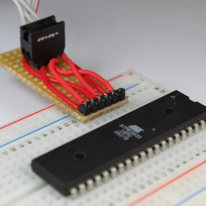
Now we will need to get more in-depth with the programming. However before we can
get a program loaded onto the chip, we need a good way to connect the SPI (Serial
Peripheral Interface) connector to the chip. We couldn't very well shove the connector
into the pins of the microcontroller, now could we? And sticking wires in the end
of the connector and into the breadboard is flimsy, unattractive, and possibly harmful
to the MCU if a wire carrying voltage is accidentally applied to the wrong pin.
Therefore to maximize our chance of success and standardize each and every connection
attempt, we will construct a small board that contains a header (little metal pins
that stick up) that the SPI connector can use, and also a header that will correspond
to the appropriate pins on the microcontroller. The latter can simply be a single
row of six pins since the makers of the Atmel AVR Atmega32 microcontroller so thoughtfully
located these pins together. This will allow us to make our MCU interface board
with a very narrow size, which will reduce the area covered on the breadboard (as
can be seen in the video). Oh yeah, the video contains a bit of soldering, so you
can learn that too!
 Ok, so to reiterate
from the last tutorial, there is a programmer that is needed between the computer
and the microcontroller. It should be noted that there are several different programmers
that can be used, and a suitable model can be had from either
Adafruit Industries (USBTinyISP) or
Sparkfun (Pocket AVR). Some of these programmers look totally different
from others, but all of them basically do the same thing--provide an interface between
the computer and the AVR microcontroller. That's it! Note that if you are not using
the AVR Atmega32 microcontroller, then you must check the compatibility of the programmer
you choose to use. Also note that many of these programmers use the same drivers,
an issue which we will get to in the next tutorial.
Ok, so to reiterate
from the last tutorial, there is a programmer that is needed between the computer
and the microcontroller. It should be noted that there are several different programmers
that can be used, and a suitable model can be had from either
Adafruit Industries (USBTinyISP) or
Sparkfun (Pocket AVR). Some of these programmers look totally different
from others, but all of them basically do the same thing--provide an interface between
the computer and the AVR microcontroller. That's it! Note that if you are not using
the AVR Atmega32 microcontroller, then you must check the compatibility of the programmer
you choose to use. Also note that many of these programmers use the same drivers,
an issue which we will get to in the next tutorial.
The connection between the computer and the MCU is really quite simple, so there should be no reason to be afraid of (or timid with) doing these steps to get a program into the microcontroller. So, let's get to it! Remember that the purpose of making such an interface board, is to insure a proper connection each and every time we need to load our program into the MCU. So if you want to make a board like I've shown in the video, then just get out your soldering iron. Don't be afraid, get it out! Well, you should be careful, as it gets hot. But don't let that get in your way. Just make sure to read all of the manufacturer's instructions on the proper operation of the soldering iron. Also, don't forget to wear goggles; and don't breath the solder fumes. Some people use a suction fan to get the fumes away from the workspace.
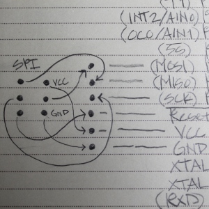
Check out the diagram above. Yes, it's a bit messy, but I drew this while caffeine was flowing through my system! The SPI connector pin-out is to the left. There are arrows from this SPI interface block to the corresponding pins on the AVR Atmega32 microcontroller. There will be no need for fancy components to complicated this process, so don't worry--we are only connecting wires from the SPI device to the pins of the microcontroller.
Let's run through the connections between the SPI device and the MCU:
- Top left SPI pin is connected to the MISO (Master In Slave Out)
- Middle Left SPI pin is connected to the SCK (the clock pin)
- Bottom Left SPI pin is connected to the Reset (Reset just does exactly what is says, and you can be sure we will talk about this pin later!)
- Bottom Right SPI pin is connected to the GND (Ground, or zero volts)
- Middle Right SPI pin is connected to the MOSI (Master Out Slave In)
- Top Right SPI pin is connected to the VCC (+5 Volts, if you want, you can go check voltage requirements in the
summary, or the
HUGE manual, and trust me, this is not an easy read!).
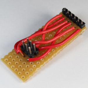
That's it!! All you need to do now is solder the wires between the two sets of headers (remember this term? They're just pins that stick up and insert into a female header). Note that the picture near the top of this page shows the female header plugged into the male header. Once these wires are all connected and soldered-up, it should look something like these pictures. However, if you want to get crazy and do it differently, please go for it!! I encourage creativity.
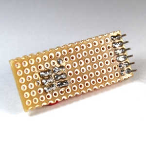
As can be seen in the pictures, the connections from the wires to the headers are made using solder bridges. A solder bridge is just solder that "blobs" together to connect two locations. These blobs sort of look like little figure 8's, or infinity symbols. And, it's not too hard to create these bridges. All you need to do is solder the two wire/pin connections like normal, and then add just a little more solder while holding the iron over both of the connections. This will provide enough solder to create the bridge. However, there is the possibility that they won't bridge. Ah, the bane of existence for most solderers...! The bridge is generally not advised in most applications; but in this case, it's simply the easiest way to make the connections between the SPI and MCU pins, and the corresponding wires that connect them. Once you have enough solder applied, and the hot iron is over the two connection, pull the iron straight up along the pin and the bridge should be maintained. Otherwise you may destroy the bridge if the hot iron is allowed to once again make contact with the main body of the bridge. Don't worry--the video shows this very nicely, and you should get the hang of it pretty quickly.
So, wasn't that easy? Now, we will get into the software part of it in the next tutorial. We will find the software on the internet to: First, recognize and drive the USBTinyISP programmer (or, if you choose, the Pocket AVR Programmer); and second, install the development environment. Note that by "driver," I mean to install a driver under the Windows OS, and the "development environment" is simply the application you will use to write the programs that will later be transferred to the chip. If you are using installing this program on another OS, like Linux or the Mac, you will still be able to follow along. Here and there, I may speak of those other wonderful operating systems and how to do things (or find the resources that will help). The programming is the same, but the development environment will probably be slightly different.